Precision & Compliance in Medical Device and Pharmaceutical Manufacturing
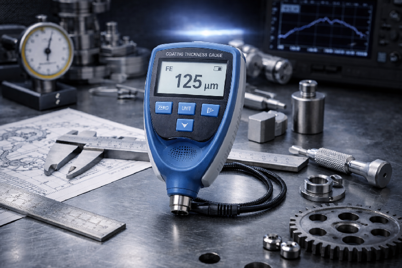
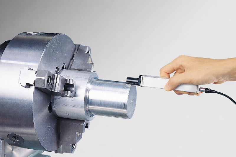
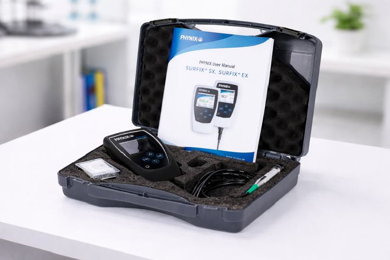
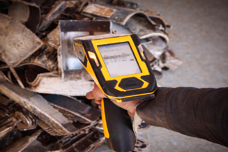
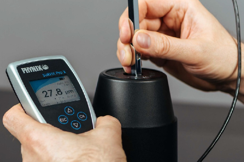
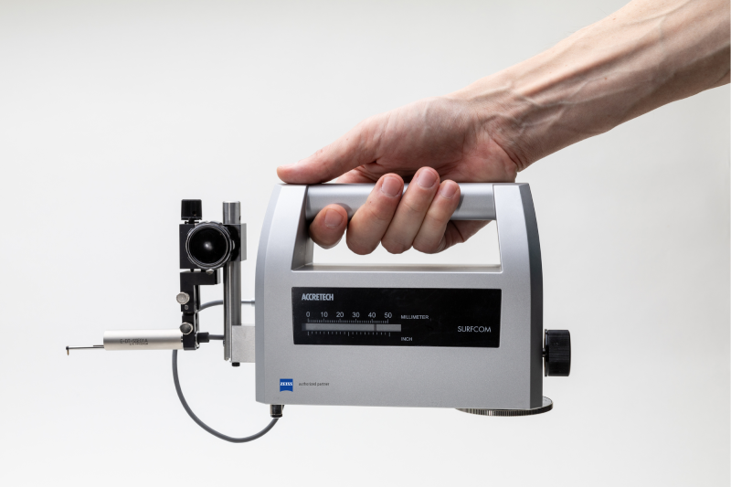
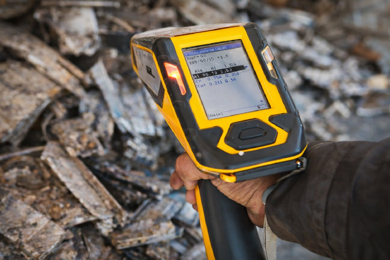
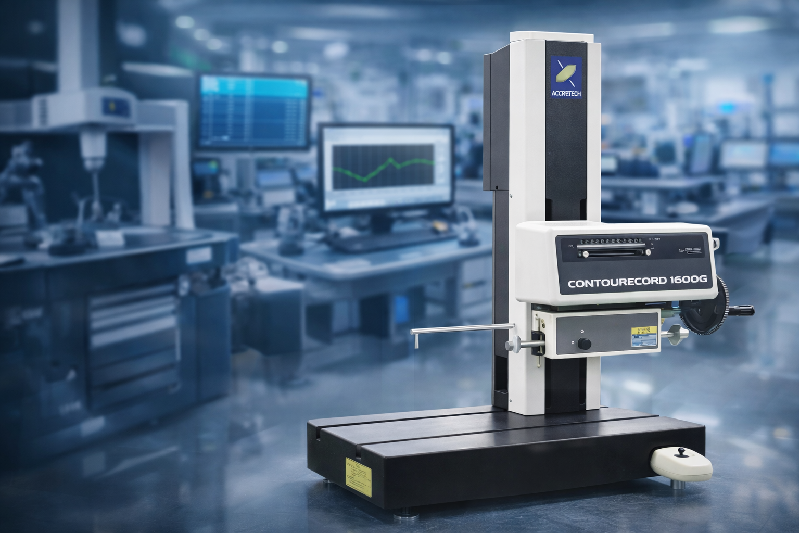
In the medical device and pharmaceutical industry, precision is not merely a competitive edge , it is a regulatory, clinical, and ethical requirement. Whether manufacturing orthopedic implants, surgical instruments, dental components, or pharmaceutical processing equipment, there is absolutely zero room for defects. Even the smallest deviation , a micron-level dimensional error, inconsistent surface finish, incorrect material composition, or uneven coating thickness , can jeopardize patient safety, delay regulatory approvals, and significantly impact brand reputation. To comply with global standards such as FDA regulations and ISO 13485, manufacturers must implement advanced metrology and inspection systems, including – CMM (Coordinate Measuring Machine) Surface Roughness Tester Handheld XRF Machines Coating Thickness Gages Digital inspection and traceability solutions This article outlines the critical challenges faced by the medical device and pharmaceutical sector and explains how advanced metrology systems enable defect-free, compliant, and audit-ready manufacturing. Key Challenges in Medical Device & Pharmaceutical Manufacturing 1) Zero Tolerance for Defects in Implants & Surgical Instruments Medical components demand exceptional accuracy and flawless execution. Implants must integrate seamlessly within the human body, and surgical instruments must function reliably in high-risk procedures. Core Challenges – Micron-level dimensional precision requirements Complex geometries with strict GD&T compliance Risk of mechanical or functional failure Extensive regulatory documentation Solution – CMM – Spectrum & Contura (Coordinate Measuring Machine) High-precision CMM systems deliver – Accurate 3D dimensional inspection Complete GD&T validation Automated, repeatable measurement routines Digital reporting for regulatory compliance By integrating advanced CMM technology, manufacturers reduce rejection rates, improve process capability (Cp, Cpk), and maintain consistent dimensional accuracy across production batches. 2) Surface Finish & Biocompatibility Requirements Surface characteristics play a vital role in – Implant osseointegration Friction control in surgical instruments Minimizing bacterial adhesion Long-term device stability Even minor surface imperfections can influence performance outcomes and regulatory acceptance. Solution – Surface Roughness Tester A high-precision Surface Roughness Tester enables manufacturers to measure – Ra (Roughness Average) Rz (Mean Peak-to-Valley Height) Waviness parameters Micro-surface deviations With accurate surface measurement, manufacturers ensure implants meet strict biocompatibility requirements while enhancing durability and long-term reliability. 3) Regulatory Compliance & Inspection Traceability (FDA / ISO 13485) Medical manufacturers are required to maintain – Complete inspection traceability Audit-ready measurement documentation Validated process records Secure digital quality data Manual or fragmented reporting systems increase the risk of compliance gaps. Solution – Digital Reporting & QMS Integration Modern metrology systems provide – Automated inspection reporting Secure digital data storage Seamless integration with Quality Management Systems (QMS) Immediate access to audit documentation This ensures readiness for FDA inspections and ISO 13485 audits at any stage. 4) Material Grade Verification Prior to Machining Medical components frequently use high-performance materials such as – Titanium alloys Medical-grade stainless steel Specialized biomedical metals Processing incorrect material grades can result in regulatory violations and severe safety risks. Solution – Handheld XRF Machines Advanced Handheld XRF Machines offer – Instant elemental analysis Accurate alloy identification Incoming raw material inspection Supplier quality validation By verifying material composition before machining, manufacturers prevent costly errors and strengthen compliance documentation. 5) Coating Thickness Validation for Surgical Instruments Many surgical tools and implants require protective coatings to ensure – Corrosion resistance Sterilization durability Extended operational lifespan Inconsistent coating thickness may lead to premature degradation and performance issues. Solution – Coating Thickness Gages High-precision Coating Thickness Gages allow manufacturers to – Measure coating layer thickness accurately Validate uniformity across production batches Ensure corrosion protection standards are met Enhance product durability Reliable coating inspection improves both functional performance and regulatory confidence. Why Advanced Metrology Is Critical in Medical Manufacturing? In medical device and pharmaceutical production, inspection is not simply quality control , it is a proactive risk management strategy. By integrating – CMM (Coordinate Measuring Machine) Surface Roughness Tester Handheld XRF Machines Coating Thickness Gages Digital reporting and traceability systems manufacturers can achieve – ✔ Defect-free components✔ Superior surface finish control✔ Audit-ready regulatory documentation✔ Reduced recall risks✔ Enhanced patient safety✔ Stronger brand credibility Strategic Benefits for Medical Manufacturers Advanced metrology solutions deliver measurable business advantages – Faster product validation cycles Improved production consistency Lower scrap and rework rates Stronger supplier quality assurance Long-term process stability Precision measurement directly impacts regulatory approval timelines, product reliability, and global competitiveness. The medical device and pharmaceutical industry requires a proactive, precision-driven approach to quality control. Advanced metrology solutions , including CMM systems, Surface Roughness Testers, Handheld XRF Machines, and Coating Thickness Gages, empower manufacturers to meet the highest standards of safety, compliance, and performance. Get Perfect Coating Gauge for Your Industry