

QS Metrology | Portable XRF Analyser | Portable XRF Spectrometer | Optical Emission spectrometer | XRD | Surface roughness Tester | roughness measuring machine | Portable Roughness Tester | Contour measuring machine | Contour Tester | Coordinate measuring machine | 3 D Coordinate measuring machine | Weld penetration inspection | Weld penetration measurement System | Stereomicroscope | Coating thickness tester | Video Measuring machine | Metallurgical Image analysis | Metallurgical microscope

admin

How Precision Engineering Companies Can Improve Part Accuracy with Contour Measurement Systems

How Precision Engineering Companies Can Improve Part Accuracy with Contour Measurement Systems

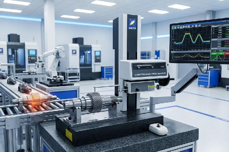
In precision engineering, even the smallest dimensional deviation can have significant consequences. A slight profile variation in a machined component can lead to assembly issues, product failures, customer complaints, costly rework, and production delays. As industries continue to demand tighter tolerances and higher quality standards, manufacturers are under constant pressure to improve measurement accuracy throughout the production process. Traditional inspection methods often struggle to capture complex profiles and contours with the precision required for modern engineering applications. This is where a Contour Measurement Machine becomes an invaluable tool. By providing highly accurate profile analysis and dimensional verification, contour measurement systems help manufacturers identify deviations early, reduce scrap, and ensure every component meets exact design specifications. In this article, we’ll explore how precision engineering companies can significantly improve part accuracy using advanced contour measurement technology. Table of Contents Why Part Accuracy Matters in Precision Engineering What Is a Contour Measurement Machine? How Contour Measurement Systems Improve Part Accuracy Key Features to Look for in a Contour Measuring Instrument Applications in Precision Engineering and Machining Business Benefits of Investing in a Contour Measuring Machine Conclusion FAQs Why Part Accuracy Matters in Precision Engineering? Precision engineering companies manufacture components that often operate in demanding environments where accuracy is non-negotiable. Whether producing automotive parts, aerospace components, medical devices, molds, dies, or high-precision machined parts, dimensional consistency directly affects product performance. A minor profile error can create multiple downstream challenges, including: Increased scrap and rework Assembly failures Reduced product lifespan Customer complaints Production delays Higher quality costs For manufacturers working with micron-level tolerances, relying solely on conventional measurement methods is no longer enough. Advanced contour inspection has become a critical part of modern quality assurance strategies. What Is a Contour Measurement Machine? A Contour Measurement Machine is a high-precision metrology system designed to measure and analyze the profile, contour, and geometric characteristics of a component. Unlike basic dimensional measuring tools, contour measurement systems accurately evaluate complex shapes, curves, angles, radii, grooves, and surface transitions. Often referred to as a Contour Machine, Contour Measuring Instrument, contour tracer, or contour tracer machine, these systems use precision probes and advanced software to compare actual part geometry against CAD models or engineering drawings. The result is highly reliable data that helps quality teams verify whether manufactured components meet specified tolerances before they move further through production. How Contour Measurement Systems Improve Part Accuracy How Do Contour Measuring Machines Detect Deviations Early? One of the biggest advantages of a contour measuring machine is its ability to identify profile deviations before they become larger production issues. When manufacturers inspect parts during production rather than after completion, they can quickly detect: Tool wear Machine drift Incorrect machining parameters Material inconsistencies Setup errors Early detection enables corrective action before hundreds or thousands of defective parts are produced. How Does Contour Measurement Improve Tolerance Control? Modern engineering drawings often include intricate contours and geometric tolerances that are difficult to verify using calipers, micrometers, or manual gauges. A contour measuring system can accurately evaluate: Radius measurements Angles Heights Depths Distances Geometric profiles Form deviations This detailed inspection capability ensures every manufactured component remains within specified tolerance limits. How Does a Contour Tracer Improve Process Stability? Manufacturing consistency depends heavily on process stability. Without accurate measurement feedback, small process variations can gradually impact product quality. A contour tracer provides detailed measurement data that helps manufacturers: Monitor process capability Track production trends Identify recurring quality issues Optimize machining parameters Improve repeatability Over time, this data-driven approach significantly enhances manufacturing consistency and overall product quality. What Features Should You Look for in a Contour Measuring Instrument? Not all contour measurement systems offer the same capabilities. When evaluating a solution, quality managers should focus on features that directly impact measurement accuracy and operational efficiency. High Measurement Accuracy The primary purpose of a contour measurement system is to deliver precise results. Look for systems capable of measuring complex geometries with exceptional repeatability and minimal measurement uncertainty. Advanced Analysis Software Modern contour machines provide powerful software for: CAD comparison Profile evaluation Automated reporting Tolerance analysis Statistical quality control These features help quality teams make faster and more informed decisions. Automation Capabilities Automated measurement routines reduce operator dependency and improve inspection consistency across shifts and production batches. Flexible Measurement Range A versatile system should accommodate a wide variety of component sizes and geometries commonly found in precision machining environments. Industry-Proven Reliability Manufacturers often choose globally trusted solutions such as the ZEISS Contour Measuring Machine because of their proven accuracy, advanced software integration, and long-term reliability in demanding industrial applications. Applications of Contour Measurement in Precision Engineering Contour measurement technology supports a broad range of precision engineering applications. CNC Machined Components Verify profiles, grooves, threads, radii, and complex contours with exceptional accuracy. Automotive Manufacturing Inspect engine components, transmission parts, fuel system components, and safety-critical assemblies. Aerospace Components Ensure compliance with stringent dimensional requirements and regulatory standards. Tool and Die Manufacturing Validate mold cavities, cutting tool profiles, and precision die geometries. Medical Device Production Maintain strict dimensional control for implants, surgical instruments, and precision medical components. In each of these applications, accurate contour inspection directly contributes to higher product quality and lower manufacturing risk. What Are the Business Benefits of Investing in a Contour Measuring Machine? While accuracy remains the primary objective, the business impact extends far beyond measurement itself. Reduced Scrap and Rework Detecting deviations early prevents defective products from progressing through production. Improved Customer Satisfaction Consistently accurate components lead to fewer complaints and stronger customer relationships. Faster Root Cause Analysis Detailed contour data helps quality teams identify and resolve manufacturing issues more quickly. Increased Production Efficiency Automated inspection reduces manual measurement time and improves throughput. Stronger Competitive Advantage Manufacturers that consistently deliver high-quality parts gain greater trust from customers and secure more long-term contracts. According to industry best practices, companies that implement advanced metrology solutions often experience measurable improvements in process capability, quality performance, and operational profitability. Conclusion In today’s precision engineering environment, achieving exceptional part accuracy requires more than skilled
How Machine Vision Systems Help Packaging Manufacturers Achieve Zero-Defect Production

How Machine Vision Systems Help Packaging Manufacturers Achieve Zero-Defect Production

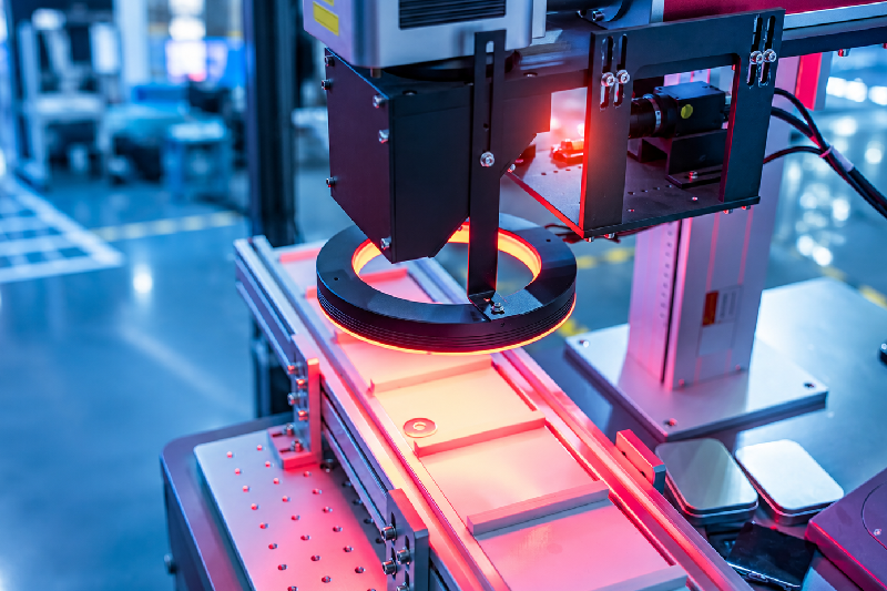
In the packaging industry, even the smallest defect can lead to costly consequences. A missing label, incorrect barcode, damaged seal, or misprinted batch number can result in customer complaints, product recalls, compliance issues, and brand reputation damage. As production lines become faster and customer expectations continue to rise, relying solely on manual inspection is no longer enough. Human inspectors can become fatigued, miss defects, and struggle to keep pace with high-speed packaging operations. This is where a machine vision system becomes a game-changer. Modern packaging manufacturers are increasingly investing in automated inspection technologies to ensure every product leaving the production line meets quality standards. A machine vision system can inspect thousands of packages per minute with exceptional accuracy, helping manufacturers move closer to the goal of zero-defect production. In this article, we’ll explore how machine vision technology helps packaging companies improve quality, reduce waste, and enhance operational efficiency. Table of Contents What Is a Machine Vision System? Why Zero-Defect Production Matters in Packaging How Machine Vision Systems Detect Packaging Defects Key Benefits of Machine Vision in Packaging Manufacturing Applications of Machine Vision Systems in Packaging Lines How to Choose the Right Vision System Conclusion FAQs What Is a Machine Vision System? A machine vision system is an automated inspection solution that uses cameras, lighting, sensors, and intelligent software to capture and analyze images during production. Unlike manual inspection, a machine vision system continuously monitors products moving through the packaging line and instantly identifies defects or deviations from predefined quality standards. A typical vision system machine consists of: Industrial cameras Smart lighting systems Image processing software Artificial intelligence algorithms Inspection and reporting tools Together, these components create a highly reliable quality control process that operates 24/7 without fatigue or inconsistency. Why Does Zero-Defect Production Matter in Packaging? Packaging is often the first thing customers notice about a product. Even if the product inside is perfect, packaging defects can negatively impact customer trust. Common packaging defects include: Missing or incorrect labels Damaged packaging Barcode printing errors Seal integrity failures Incorrect date coding Misaligned graphics Foreign object contamination These issues can lead to: Product recalls Regulatory penalties Increased waste Customer dissatisfaction Higher operational costs For manufacturers operating in food, pharmaceutical, cosmetics, consumer goods, and industrial sectors, maintaining packaging quality is critical. Achieving zero-defect production helps ensure compliance, customer satisfaction, and long-term profitability. How Machine Vision Systems Detect Packaging Defects Real-Time Inspection at High Speeds One of the biggest advantages of a machine vision system is its ability to inspect products in real time. As products move through the packaging line, high-speed cameras capture detailed images. The software then compares each image against predefined quality parameters within milliseconds. Any defective product is automatically identified and can be removed from the production line before reaching customers. This process eliminates delays while maintaining consistent quality standards. Accurate Detection Beyond Human Capability Human inspectors can miss subtle defects, especially during long shifts or high-volume production runs. A vision system can detect: Tiny print defects Label positioning errors Color inconsistencies Missing components Damaged packaging surfaces Barcode readability issues Because inspection criteria remain consistent, every product is evaluated using the same standards. Automated Decision-Making Advanced Machine vision solutions can automatically classify products as pass or fail. This automation enables: Faster quality control Reduced human intervention Lower labor costs Improved production efficiency Manufacturers can also generate inspection reports for traceability and compliance purposes. What Are the Key Benefits of Machine Vision in Packaging Manufacturing? Improved Product Quality Consistent inspection ensures defective products are identified before shipment. By reducing the chances of defective packaging reaching customers, manufacturers can strengthen brand reputation and customer trust. Reduced Waste and Rework Defects detected early in the production process are significantly less expensive to fix. A machine vision system helps manufacturers: Minimize material waste Reduce rework costs Lower scrap rates Improve resource utilization Higher Production Efficiency Unlike manual inspectors, machine vision systems operate continuously without breaks. This allows manufacturers to: Increase line speeds Reduce bottlenecks Improve throughput Maximize equipment utilization Better Regulatory Compliance Industries such as pharmaceuticals and food packaging face strict regulatory requirements. Machine vision inspection provides documented proof that products meet quality standards, simplifying audits and compliance reporting. Data-Driven Quality Improvement Modern vision system machine solutions generate valuable production data. Quality teams can analyze trends, identify recurring issues, and implement corrective actions before problems escalate. This continuous improvement approach helps manufacturers maintain long-term operational excellence. How Are Machine Vision Systems Used in Packaging Lines? Packaging manufacturers use machine vision technology across various stages of production. Label Inspection The system verifies: Correct label placement Label presence Print quality Product identification accuracy Barcode Verification A vision system checks barcode readability and accuracy to prevent supply chain disruptions. Seal Inspection Machine vision detects damaged or incomplete seals that could compromise product safety. Date Code and Batch Number Verification The system confirms that expiration dates, batch codes, and lot numbers are correctly printed and legible. Package Integrity Inspection High-resolution cameras identify: Dents Tears Missing components Surface defects These inspections ensure only high-quality products reach the market. How Do You Choose the Right Vision System for Packaging Applications? When selecting a machine vision solution, packaging manufacturers should consider: Inspection Requirements Define the types of defects you need to detect and the required inspection accuracy. Production Speed Choose a system capable of keeping up with your line speed without compromising performance. Integration Capabilities The solution should integrate seamlessly with existing production equipment and automation systems. Scalability As production demands grow, the system should support future expansion and additional inspection requirements. Vendor Expertise Partner with a trusted provider experienced in packaging inspection applications and quality control automation. Conclusion Achieving zero-defect production is no longer an unrealistic goal for packaging manufacturers. With increasing quality expectations, regulatory requirements, and production pressures, automated inspection has become essential rather than optional. A modern machine vision system enables manufacturers to identify defects in real time, reduce waste, improve efficiency, and maintain consistent product quality across every production run. By replacing subjective manual inspections with

How Manufacturing QA Teams Can Improve Product Quality with Coating Thickness Measurement

How Manufacturing QA Teams Can Improve Product Quality with Coating Thickness Measurement

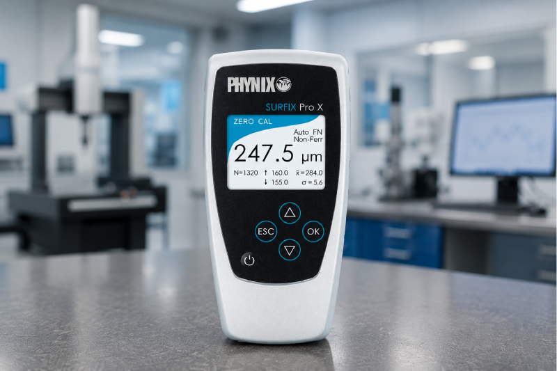
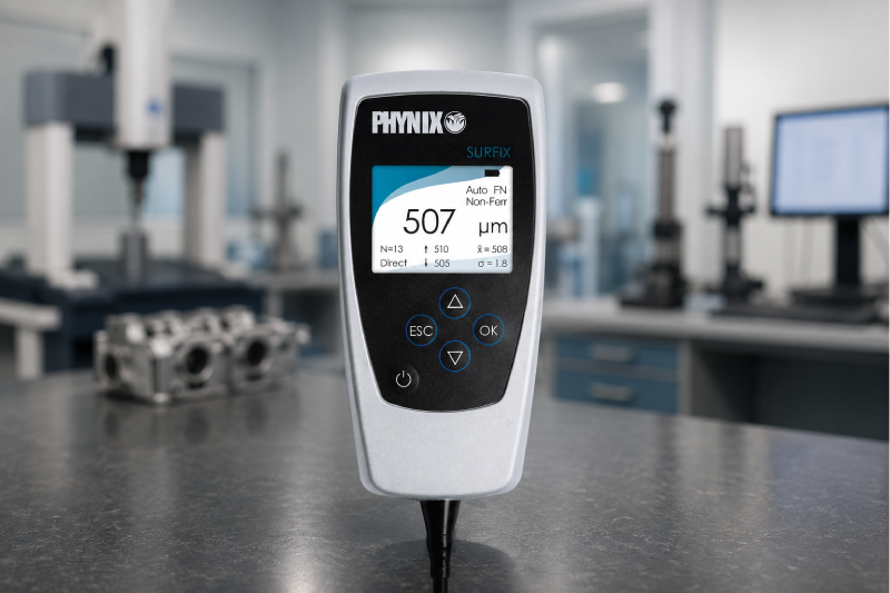
In manufacturing, quality isn’t just about producing a part that looks good—it’s about ensuring that every product performs reliably in the real world. Yet many manufacturers continue to face issues such as premature corrosion, coating failures, customer complaints, product rejections, and costly rework. In many cases, these problems can be traced back to one overlooked factor: incorrect coating thickness. Whether you’re applying paint, powder coating, galvanization, or protective surface treatments, maintaining the correct coating thickness is critical. Too little coating can expose products to corrosion and wear, while excessive coating can lead to adhesion issues, cracking, and unnecessary material costs. This is where a coating thickness gauge becomes an essential tool for Manufacturing QA teams. By accurately measuring coating thickness during production and inspection, manufacturers can improve consistency, reduce defects, and ensure compliance with customer specifications and industry standards. In this guide, we’ll explore how coating thickness measurement helps quality teams enhance product quality and why investing in the right measurement solution delivers long-term value. Table of Contents What Is Coating Thickness Measurement? Why Coating Thickness Matters in Manufacturing How QA Teams Use a Coating Thickness Gauge What Are the Benefits of Coating Thickness Measurement? How to Implement Effective Coating Thickness Inspection Choosing the Right Coating Thickness Tester Conclusion FAQs What Is Coating Thickness Measurement? Coating thickness measurement is the process of determining the thickness of a protective or decorative coating applied to a substrate. The measurement ensures that the coating meets predefined specifications and performs as intended. A coating thickness gauge, also known as a DFT meter (Dry Film Thickness Meter), is used to measure the thickness of coatings such as: Paint coatings Powder coatings Galvanized coatings Electroplated layers Industrial protective coatings Anodized surfaces Modern thickness measurement instruments provide fast, accurate, and non-destructive readings, allowing quality teams to inspect products without damaging them. Why Does Coating Thickness Matter in Manufacturing? Many manufacturers focus heavily on dimensions, tolerances, and visual inspections. However, coating thickness plays an equally important role in product performance and lifespan. Imagine a fabricated steel component designed for outdoor use. If the coating thickness falls below the required specification, moisture can penetrate the protective layer, leading to rust and corrosion much sooner than expected. On the other hand, excessive coating thickness can result in cracking, peeling, or poor adhesion. Incorrect coating thickness can cause: Product failures in the field Customer complaints Warranty claims Rework and scrap Increased material costs Non-compliance with industry standards For QA teams, monitoring coating thickness is not just an inspection activity—it is a proactive quality control strategy that directly impacts product reliability and customer satisfaction. How Manufacturing QA Teams Use a Coating Thickness Gauge A coating thickness gauge enables quality professionals to verify coating consistency throughout the production process. Instead of relying solely on visual inspections, inspectors obtain measurable and repeatable data. QA teams typically use coating thickness measurement during: Incoming Material Inspection Manufacturers often receive coated components from suppliers. A thickness gauge paint inspection helps verify supplier quality before materials enter production. In-Process Quality Control During coating application, inspectors can use a coating thickness tester to ensure the coating is being applied within specification. Early detection prevents large batches of defective products. Final Product Inspection Before shipment, quality teams verify that finished products meet customer requirements and industry standards. This final validation minimizes the risk of field failures. Audit and Compliance Documentation Many industries require documented quality records. Thickness measurements provide objective data that supports compliance audits and customer quality reports. What Are the Benefits of Using a Coating Thickness Gauge? How Does It Reduce Product Defects? One of the biggest advantages of coating thickness measurement is defect prevention. By detecting deviations early, manufacturers can correct issues before products reach customers. This leads to: Fewer coating failures Reduced rework Lower scrap rates Improved process control How Does It Improve Product Reliability? Products exposed to harsh environments require adequate protection against corrosion, chemicals, moisture, and wear. Accurate coating thickness measurement ensures that protective coatings perform as designed, resulting in longer-lasting products and improved customer confidence. How Does It Reduce Manufacturing Costs? Many manufacturers unknowingly waste coating materials by applying thicker layers than necessary. A DFT meter helps optimize coating application by ensuring the correct amount is applied every time. This reduces material consumption while maintaining quality standards. Benefits include: Lower paint consumption Reduced production costs Improved process efficiency Better resource utilization How Does It Support Industry Compliance? Industries such as automotive, aerospace, construction, oil & gas, and heavy engineering often specify strict coating requirements. Using a reliable coating thickness tester helps manufacturers comply with standards and customer specifications while maintaining traceable quality records. How Can QA Teams Implement Effective Coating Thickness Inspection? Successful coating inspection requires more than simply purchasing a measurement device. QA teams should establish a structured inspection process. Standardize Measurement Procedures Create documented inspection procedures that define: Inspection locations Number of measurements Acceptance criteria Reporting requirements Standardization improves consistency across operators and facilities. Train Inspection Personnel Even the most advanced coating thickness gauge can produce inaccurate results if used incorrectly. Regular training ensures inspectors understand: Proper calibration Surface preparation requirements Measurement techniques Data interpretation Monitor Trends Instead of Individual Readings Many quality issues develop gradually over time. By analyzing thickness measurement trends, QA teams can identify process drift before it results in product failures. Calibrate Equipment Regularly Routine calibration ensures measurement accuracy and maintains confidence in inspection data. Calibration should become a standard part of every quality management system. How Do You Choose the Right Coating Thickness Tester? Selecting the right instrument depends on your application, substrate material, and inspection requirements. When evaluating a coating thickness tester, consider: Measurement Accuracy Accurate readings are essential for quality decisions. Look for instruments with proven performance and repeatability. Ease of Use Operators should be able to perform inspections quickly and confidently without extensive setup. Data Storage and Reporting Modern instruments offer digital reporting capabilities that simplify quality documentation and audit preparation. Durability Manufacturing environments can be demanding. Choose equipment designed for industrial

How Metal Manufacturers Can Reduce Quality Failures with Handheld XRF Analyzers

How Metal Manufacturers Can Reduce Quality Failures with Handheld XRF Analyzers

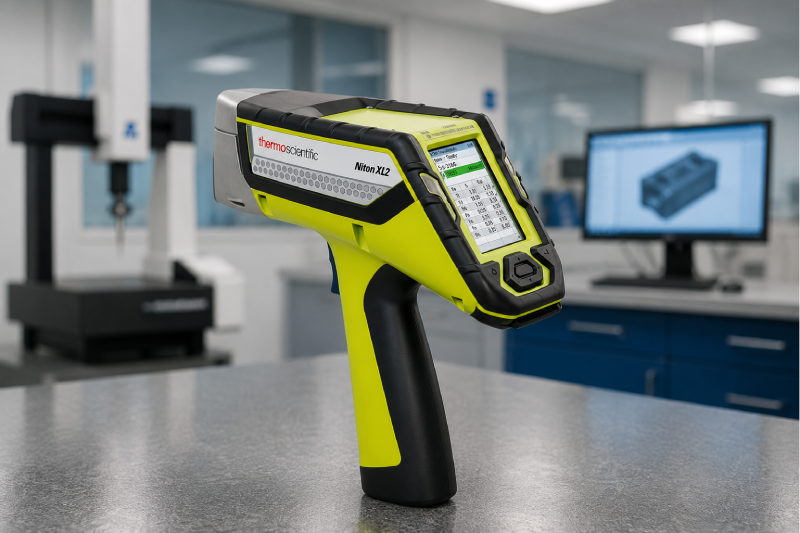
In metal and alloy manufacturing, even a small material identification error can lead to costly consequences. A single batch produced with the wrong alloy composition can result in rejected orders, production delays, customer complaints, compliance issues, and significant financial losses. For quality managers and production teams, maintaining consistent material quality is no longer just a best practice—it’s a business necessity. Yet many manufacturers still rely on traditional testing methods that are slow, labor-intensive, and often unable to provide immediate results on the shop floor. This is where handheld XRF analyzers are transforming quality control processes. By providing fast, accurate, and non-destructive material analysis in seconds, these advanced devices help manufacturers identify alloy grades, verify incoming materials, and prevent costly quality failures before they occur. In this article, we’ll explore how portable XRF technology helps metal manufacturers improve quality assurance, reduce scrap, and strengthen customer confidence. Table of Contents What Causes Quality Failures in Metal Manufacturing? What Are Handheld XRF Analyzers? How Do Handheld XRF Analyzers Reduce Quality Failures? Key Benefits of Portable XRF Analysis Industries Using XRF Technology Best Practices for Implementation Conclusion FAQs What Causes Quality Failures in Metal Manufacturing? Quality failures often begin long before the final product reaches the customer. In many cases, the root cause can be traced back to incorrect material identification, alloy mix-ups, contamination, or inconsistent raw material quality. Common quality issues include: Wrong alloy grade selection Mixing of similar-looking metals Supplier material inconsistencies Human inspection errors Lack of incoming material verification Inadequate traceability processes These issues can lead to: Increased scrap rates Product recalls Rework and production downtime Customer dissatisfaction Regulatory non-compliance For manufacturers operating in competitive markets, preventing these failures is essential for profitability and reputation. What Are Handheld XRF Analyzers? Handheld XRF analyzers are portable instruments that use X-ray fluorescence technology to identify the elemental composition of metals and alloys within seconds. An x ray fluorescence analyzer works by directing X-rays onto a material’s surface and measuring the fluorescent energy emitted by the elements present. This allows operators to instantly determine alloy composition without damaging the material. Unlike traditional laboratory testing, modern xrf analyzers deliver real-time results directly on the production floor, warehouse, or receiving dock. Today’s advanced xrf machines are widely used for: Positive Material Identification (PMI) Alloy verification Incoming material inspection Scrap sorting Quality assurance testing Supplier validation How Do Handheld XRF Analyzers Reduce Quality Failures? 1. Verify Incoming Raw Materials Before Production One of the most common causes of manufacturing defects is the use of incorrect raw materials. Suppliers may unintentionally deliver materials with the wrong composition, mislabeled batches, or mixed inventory. Without proper verification, these materials can enter production and create widespread quality issues. Using handheld XRF analyzers, quality teams can inspect every incoming batch within seconds and verify alloy grades before materials are accepted into inventory. This simple step dramatically reduces the risk of material-related defects. 2. Prevent Alloy Mix-Ups on the Shop Floor Many alloys appear visually identical despite having significantly different chemical compositions. For example, certain grades of stainless steel can look nearly identical but perform very differently in critical applications. A portable x ray fluorescence machine allows operators to quickly verify materials during production, ensuring the correct alloy is used at every stage. This reduces human error and eliminates costly mix-ups. 3. Improve Positive Material Identification (PMI) Positive Material Identification has become a critical quality requirement across many industries. Manufacturers supplying aerospace, automotive, oil & gas, and power generation sectors often need documented proof of material composition. Modern xrf analyzers provide instant PMI results that support quality documentation and compliance requirements. This not only reduces quality failures but also strengthens customer trust. 4. Reduce Scrap and Rework Costs When material issues are discovered after production, the consequences can be expensive. Manufacturers may need to: Scrap finished products Rework components Delay shipments Repeat testing procedures Portable XRF analysis helps identify material problems before production begins, significantly reducing waste and avoiding unnecessary costs. For many facilities, the savings generated through scrap reduction alone can justify the investment in an analyzer. 5. Strengthen Supplier Quality Control Supplier performance directly impacts manufacturing quality. By incorporating handheld XRF analyzers into supplier verification programs, manufacturers can ensure every shipment meets required specifications. This proactive approach creates accountability throughout the supply chain and helps maintain consistent product quality. What Are the Key Benefits of Portable XRF Analysis? The advantages extend far beyond simple material identification. Faster Decision-Making Results are available within seconds, enabling immediate quality decisions without waiting for laboratory reports. Non-Destructive Testing Materials remain intact during testing, eliminating unnecessary waste. Increased Productivity Operators can perform inspections directly on the production floor, reducing delays and bottlenecks. Better Compliance Accurate documentation supports quality certifications and industry standards. Improved Customer Confidence Consistent material verification helps manufacturers deliver reliable products every time. Which Industries Benefit Most from XRF Technology? Portable XRF technology is widely used across metal and alloy manufacturing sectors. Industries include: Steel manufacturing Foundries Metal fabrication Aerospace manufacturing Automotive component production Oil & gas equipment manufacturing Heavy engineering Power generation Mining and metallurgy Even though some businesses may associate an xrf gold testing machine primarily with precious metal analysis, the same technology plays a vital role in industrial alloy verification and quality control. How Should Manufacturers Implement Handheld XRF Analysis? To maximize results, manufacturers should integrate XRF testing throughout the production process. Recommended Best Practices Verify Incoming Materials Test all incoming batches before acceptance. Establish PMI Checkpoints Perform alloy verification at critical production stages. Train Operators Ensure quality teams understand proper testing procedures. Maintain Calibration Regular calibration improves accuracy and consistency. Create Digital Records Store inspection data for traceability and audits. When implemented correctly, portable XRF becomes a powerful quality assurance tool rather than just a testing device. Conclusion Quality failures can be extremely costly for metal manufacturers, but many of them are preventable. By using handheld XRF analyzers, manufacturers gain the ability to verify materials instantly, prevent alloy mix-ups, improve supplier quality control, and reduce scrap before problems impact

How Surface Roughness Testers Improve Quality Control in Automotive CNC Machining

How Surface Roughness Testers Improve Quality Control in Automotive CNC Machining?

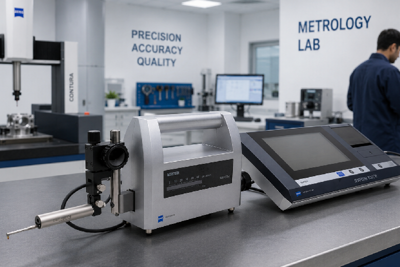
In automotive CNC machining, even the smallest surface imperfection can lead to major performance issues. A poorly finished engine shaft, brake component, or transmission gear may increase friction, reduce durability, and trigger expensive product recalls. That’s why manufacturers today are placing greater focus on precision surface inspection than ever before. Modern automotive production lines are built around consistency, speed, and micron-level accuracy. But achieving that level of precision is impossible without the right quality control tools. This is where a surface roughness tester becomes essential. Whether you manufacture engine blocks, crankshafts, gears, pistons, or EV components, a reliable surface roughness measurement instrument helps ensure every machined part meets strict automotive standards. It reduces rework, minimizes defects, improves coating adhesion, and supports long-term product performance. In this blog, we’ll explore how surface roughness testers improve quality control in automotive CNC machining, why they matter in modern manufacturing, and how choosing the right inspection solution can help manufacturers stay competitive. Table of Contents What Is a Surface Roughness Tester? Why Surface Finish Matters in Automotive CNC Machining How Surface Roughness Testers Improve Quality Control Key Applications in Automotive Manufacturing Benefits of Using Portable Surface Roughness Testers How to Choose the Right Surface Roughness Measurement Equipment Conclusion FAQs What Is a Surface Roughness Tester? A surface roughness tester is a precision inspection tool used to measure the texture and finish quality of machined surfaces. It evaluates microscopic peaks and valleys on a component’s surface to determine whether it meets required engineering standards. A modern surface roughness measurement device helps manufacturers analyze critical parameters such as: Ra (Average Roughness) Rz (Mean Peak-to-Valley Height) Rt (Maximum Roughness Depth) Rq (Root Mean Square Roughness) These measurements are vital in automotive manufacturing because surface finish directly affects friction, wear resistance, lubrication performance, sealing capability, and overall component lifespan. Today’s advanced surface roughness measurement equipment is widely used across CNC machining centers, automotive QA labs, and production lines to ensure precision and consistency. Why Does Surface Finish Matter in Automotive CNC Machining? Automotive components operate under high pressure, constant friction, and extreme temperatures. Even minor surface inconsistencies can compromise performance and reliability. Imagine a transmission gear with excessive surface roughness. The uneven finish increases friction between mating parts, leading to premature wear and reduced fuel efficiency. Similarly, rough engine components can negatively affect lubrication flow and heat distribution. This is why automotive manufacturers rely heavily on surface roughness testing machines during CNC machining operations. A controlled surface finish helps: Improve component durability Reduce friction and wear Enhance coating and paint adhesion Increase sealing performance Minimize vibration and noise Ensure compliance with automotive quality standards For high-volume automotive production, maintaining repeatable surface quality is no longer optional—it’s essential for both safety and profitability. How Surface Roughness Testers Improve Quality Control in Automotive CNC Machining? 1. Detect Machining Defects Before Final Assembly One of the biggest advantages of using a surface roughness tester is early defect detection. CNC machining issues such as tool wear, incorrect cutting speed, vibration, or coolant problems often leave visible surface irregularities. Without proper inspection, these defects may only be discovered after assembly or customer complaints. Using a surface roughness meter allows QA teams to identify inconsistencies immediately and correct machining parameters before defects escalate into costly production losses. This proactive approach helps manufacturers: Reduce scrap and rework Avoid production downtime Improve first-pass yield Maintain consistent product quality In large-scale automotive manufacturing, preventing just a few rejected batches can save thousands of dollars. 2. Ensure Consistency Across High-Volume Production Automotive suppliers often produce thousands of identical components every day. Maintaining identical surface quality across every batch is a major challenge. A reliable surface roughness measurement instrument helps production teams standardize inspection processes and maintain consistent machining quality across shifts, operators, and machines. By integrating surface roughness measurement equipment into quality workflows, manufacturers can establish measurable quality benchmarks and reduce variability in production. Consistency also strengthens supplier credibility with automotive OEMs that demand strict quality compliance. 3. Improve Functional Performance of Automotive Components Surface finish directly impacts how automotive parts perform in real-world conditions. For example: Smooth bearing surfaces reduce friction Properly finished gears improve power transmission Refined brake components enhance safety Precision engine parts improve fuel efficiency Using a surface roughness testing machine ensures that every component achieves the required finish quality for optimal functionality. This becomes even more critical in electric vehicle manufacturing, where precision components require extremely fine surface tolerances for efficient operation. What Are the Key Applications of Surface Roughness Testers in Automotive Manufacturing? A portable surface roughness tester is widely used across multiple automotive machining applications, including:ible consumables may reduce fusion efficiency and weaken structural integrity. Engine Components Crankshafts Camshafts Cylinder heads Pistons Transmission Systems Gears Shafts Bearings Clutch components Brake Systems Brake discs Brake drums Calipers EV Components Battery housings Motor shafts Precision aluminum components These applications require highly controlled surface finishes to ensure safety, durability, and performance. Why Are Portable Surface Roughness Testers Becoming Popular? Modern manufacturers increasingly prefer a portable roughness tester because it offers flexibility and faster inspection directly on the production floor. Unlike traditional stationary systems, portable devices allow operators to inspect large or difficult-to-move automotive components without interrupting workflow. Key Benefits of Portable Surface Roughness Testers Faster on-site inspection Reduced machine downtime Easy operation for production teams Improved inspection efficiency Suitable for large automotive components Real-time quality monitoring For busy CNC machining environments, portability translates into higher productivity and quicker decision-making. How to Choose the Right Surface Roughness Measurement Equipment? Selecting the right surface roughness measurement device depends on your manufacturing requirements, inspection frequency, and component complexity. Here are a few important factors to consider: Measurement Accuracy Choose equipment capable of micron-level precision for automotive applications. Portability A portable surface roughness tester is ideal for shop-floor inspection and large components. Parameter Support Ensure the device supports critical automotive roughness parameters such as Ra, Rz, and Rt. Ease of Use User-friendly interfaces reduce training time and improve inspection speed. Data Reporting Advanced systems with digital reporting

Weld Penetration Inspection How to Minimize Structural Rework in Large-Scale Infrastructure

Weld Penetration Inspection: How to Minimize Structural Rework in Large-Scale Infrastructure

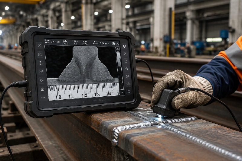
A single failed weld in a bridge, refinery, stadium, or industrial plant can trigger weeks of rework, unexpected shutdowns, and massive budget overruns. For project managers and QA teams handling large-scale infrastructure, weld quality is not just a technical requirement — it directly affects timelines, safety, compliance, and profitability. That’s where weld penetration inspection becomes critical. Incomplete weld penetration often hides beneath the surface until inspections reveal cracks, weak joints, or structural instability. By then, the cost of repair can be enormous. In high-stakes industries, even minor welding defects can delay approvals, damage client trust, and increase liability risks. The good news? With the right welding inspection process, advanced testing methods, and proactive quality control, you can detect penetration issues early and drastically reduce structural rework. This guide explains how modern weld penetration strategies help infrastructure teams improve reliability, maintain compliance, and avoid expensive mistakes. Table of Contents What Is Weld Penetration? Why Weld Penetration Matters in Infrastructure Projects Common Causes of Poor Weld Penetration How Weld Penetration Inspection Minimizes Rework Best Weld Penetration Test Methods How to Improve Welding Penetration Quality Benefits of Advanced Weld Inspection Systems Conclusion FAQs What Is Weld Penetration in Welding? Weld penetration refers to how deeply the weld metal fuses into the base material during the welding process. Proper penetration in welding ensures the joint achieves the required strength and durability needed for structural performance. When the weld penetration test is insufficient, the joint may appear acceptable externally while remaining weak internally. This hidden weakness can later cause cracking, fatigue failure, or complete structural breakdown under stress. In large-scale infrastructure projects, proper welding penetration is especially important for: Steel bridges Pressure vessels Pipelines Heavy structural fabrication Industrial plants Transportation infrastructure For QA engineers and fabrication leads, ensuring proper weld penetration is one of the most effective ways to reduce costly repairs later in the project lifecycle. Why Does Weld Penetration Matter So Much in Infrastructure Projects? Infrastructure projects operate under extreme pressure. Tight schedules, strict regulations, and large financial investments leave very little room for welding errors. Poor weld penetration creates problems that often remain invisible until advanced weld inspection is performed. By the time defects are discovered, teams may already face: Material wastage Delayed project timelines Failed compliance audits Structural safety concerns Increased labor costs Client dissatisfaction Imagine a major structural beam failing ultrasonic testing after installation. The removal, re-welding, re-inspection, and downtime can cost thousands — sometimes millions — depending on project scale. This is why leading infrastructure firms prioritize weld penetration test procedures early in fabrication instead of relying solely on final-stage inspections. What Causes Poor Weld Penetration? Understanding the root causes helps prevent recurring defects. Incorrect Welding Parameters Improper voltage, amperage, or travel speed can reduce welding penetration significantly. Low heat input often prevents complete fusion between metals. Poor Joint Preparation Improper groove angles, contamination, or uneven fit-up restrict penetration in welding and increase defect risk. Inexperienced Welders Even skilled welders can struggle with thick materials or complex structural joints without proper process control and training. Wrong Electrode or Filler Material Using incompatible consumables may reduce fusion efficiency and weaken structural integrity. Inadequate Inspection Practices Many infrastructure teams still rely heavily on visual checks. Unfortunately, visual inspection alone cannot accurately verify internal weld penetration. How Does Weld Penetration Inspection Minimize Structural Rework? The biggest advantage of proactive welding inspection is early defect detection. Instead of discovering failures after assembly or installation, advanced inspection methods identify penetration issues during fabrication itself. This allows teams to correct problems immediately before they escalate into larger structural concerns. Early Detection Prevents Costly Repairs Catching incomplete penetration during fabrication is far less expensive than repairing installed structural components. Early intervention reduces labor duplication, equipment downtime, and project disruption. Improves Regulatory Compliance Infrastructure projects must meet strict welding codes and safety standards. Consistent weld inspection ensures compliance with industry regulations and minimizes approval delays. Enhances Structural Reliability Proper weld penetration strengthens fatigue resistance, load-bearing capacity, and long-term structural durability. This is especially critical for bridges, offshore structures, and industrial facilities exposed to constant stress. Reduces Project Delays Rework is one of the leading causes of schedule overruns in fabrication projects. Reliable weld penetration testing helps maintain smoother workflows and predictable delivery timelines. Protects Brand Reputation Clients and stakeholders expect structural reliability. Consistent quality assurance builds trust and strengthens long-term business relationships. What Are the Best Weld Penetration Test Methods? Different inspection methods are used depending on material thickness, joint type, and project requirements. Ultrasonic Testing (UT) Ultrasonic testing is widely used for detecting internal penetration defects in structural welds. High-frequency sound waves identify incomplete fusion, cracks, and voids without damaging the material. Best for: Thick structural steel, pipelines, pressure vessels Radiographic Testing (RT) Radiographic inspection uses X-rays or gamma rays to reveal internal weld defects clearly. It provides highly accurate imaging for penetration analysis. Best for: Critical infrastructure and code-compliant projects Visual Weld Inspection Visual inspection remains an essential first step in welding inspection. While it cannot confirm internal penetration fully, it helps identify surface defects and alignment issues. Best for: Preliminary quality checks Macro Etch Testing This weld penetration test involves cutting and polishing a sample weld to visually evaluate penetration depth and fusion quality. Best for: Procedure qualification and welder testing Automated CMM and Digital Inspection Systems Modern fabrication facilities increasingly use automated inspection technologies for high-precision weld analysis. These systems improve consistency, reduce human error, and accelerate quality reporting. How Can You Improve Welding Penetration Quality? Reducing structural rework starts long before inspection. Standardize Welding Procedures Clear welding procedure specifications (WPS) ensure consistent penetration results across teams and projects. Invest in Welder Training Experienced welders understand how to adjust parameters based on material thickness, joint configuration, and welding position. Use Real-Time Monitoring Modern monitoring systems help track heat input, travel speed, and welding consistency during production. Perform In-Process Weld Inspection Waiting until final inspection increases rework risk. In-process checks help identify problems immediately. Adopt Advanced Inspection Technology Digital inspection systems improve defect detection

How Automated Coordinate Measuring Machine Solutions Enhance Quality Control in Semiconductor Production Lines

How Automated Coordinate Measuring Machine Solutions Enhance Quality Control in Semiconductor Production Lines

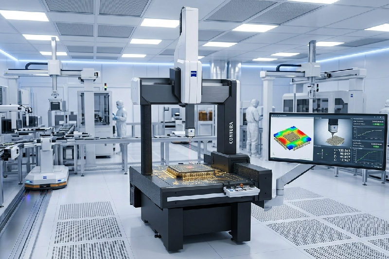
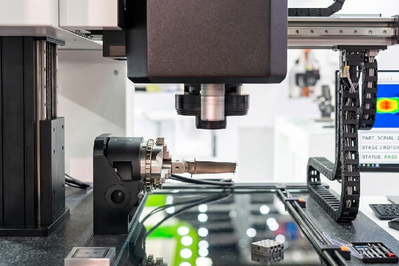
Introduction: The Hidden Cost of Tiny Errors In semiconductor manufacturing, even a micron-level deviation can turn into a costly batch rejection. If you’re a quality control manager or production head, you already know the pressure—tight tolerances, faster production cycles, and zero room for error. But here’s the real challenge: manual inspection methods and outdated measurement tools simply can’t keep up anymore. This is where a coordinate measuring machine (CMM) changes the game. More importantly, automated CMM solutions are now helping semiconductor manufacturers achieve unmatched accuracy, speed, and consistency. In this blog, you’ll discover how automated CMM systems improve quality control, reduce defects, and drive real ROI in semiconductor production lines. Table of Contents What is a Coordinate Measuring Machine (CMM)? Why Quality Control is Critical in Semiconductor Manufacturing How Automated CMM Solutions Work Key Benefits of Automated CMM in Semiconductor Production What Features to Look for in a CMM Machine How to Choose the Right CMM for Your Facility FAQs What is a Coordinate Measuring Machine (CMM)? A coordinate measuring machine (CMM) is a high-precision device used to measure the physical geometrical characteristics of a component. It uses probes or sensors to capture exact dimensions, ensuring every part meets strict design specifications. In semiconductor manufacturing, where components are incredibly small and complex, CMM measurement ensures precision down to microns—or even sub-micron levels. Whether it’s wafer inspection, PCB components, or micro-electronic parts, a CMM measuring machine ensures every detail is accurate, repeatable, and compliant with quality standards. Why Quality Control is Critical in Semiconductor Manufacturing? Semiconductor production is unforgiving. A small defect can lead to complete product failure, customer dissatisfaction, or regulatory issues. Here’s what most manufacturers struggle with: Increasing miniaturization of components Tight tolerance requirements High production volumes Pressure to reduce rejection rates Traditional inspection methods often fall short because they are slower, prone to human error, and lack consistency. That’s why many manufacturers are shifting toward automated coordinate machine solutions—to keep up with speed without compromising accuracy. How Automated CMM Solutions Work in Production Lines? Automated CMM coordinate measuring machine systems integrate directly into your production workflow. Instead of manual intervention, these machines perform measurements automatically using programmed routines. Here’s how it typically works: Parts are loaded onto the CMM system (manually or via robotic arms) The system runs pre-programmed inspection sequences Sensors or probes capture precise measurements Data is analyzed in real-time Deviations are flagged instantly This automation allows continuous inspection without slowing down production, which is critical in semiconductor environments. How Automated CMM Solutions Improve Quality Control? 1. How Automation Eliminates Human Error Manual inspection always carries variability. Even experienced operators can make mistakes under pressure. Automated CMM machines remove this risk by standardizing measurement processes. Every component is inspected using the same parameters, ensuring consistency across batches. This leads to: More reliable results Reduced rework Higher confidence in quality reports 2. How CMM Measurement Improves Accuracy at Micro Levels Semiconductor components require ultra-precise measurements. A slight deviation can affect performance or functionality. Automated CMM measurement systems provide: Sub-micron accuracy Repeatable results High-resolution data capture This level of precision is something traditional tools simply cannot achieve consistently. 3. How Automated CMM Reduces Defects and Waste One of the biggest advantages of automation is early defect detection. Instead of discovering issues at the end of production, CMM measuring machines identify deviations in real-time. This helps you: Fix problems early in the process Reduce material wastage Lower rejection rates In high-volume semiconductor production, this translates directly into cost savings. 4. How Real-Time Data Improves Decision Making Modern coordinate measuring machine systems don’t just measure—they provide actionable insights. With integrated software, you can: Monitor trends Identify recurring issues Optimize production parameters This transforms quality control from a reactive process into a proactive strategy. 5. How Automation Boosts Production Speed Speed is critical in semiconductor manufacturing. Manual inspection slows everything down. Automated CMM machines work continuously without fatigue, enabling: Faster inspection cycles Increased throughput Reduced bottlenecks This ensures your production line runs smoothly without compromising quality. What Features to Look for in a CMM Machine? Choosing the right CMM machine is crucial for maximizing ROI. Here are key features to consider: High accuracy and repeatability for micro components Automation compatibility with robotic systems Advanced software for data analysis Flexible probe systems for complex geometries Scalability for future production needs Many buyers also compare options like zeiss cmm machine, but it’s important to evaluate based on your specific production requirements rather than brand alone. How to Choose the Right Coordinate Measuring Machine? Before investing in a coordinate measuring machine, ask these critical questions: What level of accuracy do your components require? What is your production volume? Do you need inline or offline inspection? What is your budget and expected ROI? Also, consider the CMM machine price not just as a cost—but as a long-term investment. A well-chosen system can significantly reduce defects, improve efficiency, and increase profitability. Real-World Impact: Why Manufacturers Are Switching to Automated CMM Many semiconductor manufacturers have already made the shift—and the results are impressive: Up to 40% reduction in inspection time Significant drop in rejection rates Improved compliance with quality standards Better customer satisfaction This isn’t just a trend—it’s becoming the industry standard. Conclusion: Precision, Speed, and Control—All in One System If you’re still relying on manual inspection or outdated tools, you’re likely losing time, money, and efficiency. Automated coordinate measuring machine solutions bring together accuracy, speed, and intelligence, making them essential for modern semiconductor production lines. From reducing defects to improving decision-making, the benefits go far beyond measurement—they transform your entire quality control process. FAQs What is a coordinate measuring machine used for? A coordinate measuring machine (CMM) is used to measure the physical dimensions of components with high precision, ensuring they meet design specifications. How does a CMM machine improve quality control? A CMM machine improves quality by providing accurate, repeatable measurements and detecting defects early in the production process. What industries use CMM measuring machines? Industries like semiconductor manufacturing, electronics, automotive, and aerospace widely

Contour Measurement Machine Price vs ROI A Guide for Precision Manufacturers

Contour Measurement Machine Price vs ROI: A Guide for Precision Manufacturers

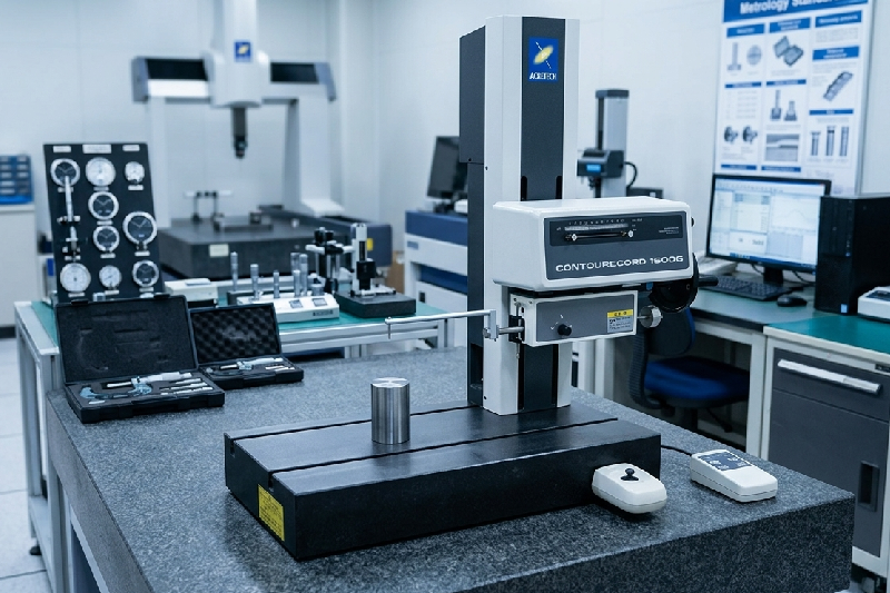
Let’s be honest—no plant manager likes spending lakhs on a new machine unless the returns are crystal clear. And when it comes to a contour measurement machine, the first question is always: “Is this really worth the investment?” In high-speed steel manufacturing, even a tiny profile deviation can lead to batch rejection, rework, or worse—customer complaints. Traditional inspection methods simply can’t keep up anymore. This is where a modern contour measuring machine or contour tracer steps in. In this guide, we’ll break down the real cost vs ROI of investing in a contour measuring instrument—so you can make a confident, data-backed decision for your plant. Table of Contents What is a Contour Measurement Machine? Why Steel Manufacturers Struggle Without It? Contour Measurement Machine Price: What You’re Really Paying For? ROI Breakdown: How It Pays You Back? Real Benefits for High-Speed Production Lines How to Choose the Right Contour Machine? Conclusion FAQs What is a Contour Measurement Machine? A contour measurement machine (also known as a contour tracer or contour measuring instrument) is used to measure the profile and geometry of components with extreme precision. It captures surface contours, edges, radii, angles, and complex shapes that are critical in steel and precision machining. Unlike manual gauges or basic measuring tools, a contour tracer machine gives you: High-resolution profile analysis Repeatable and consistent results Digital reports for quality audits Integration with automated inspection systems For steel manufacturers dealing with high volumes and tight tolerances, this isn’t just a measuring tool—it’s a quality control backbone. Why Steel Manufacturers Struggle Without a Contour Measuring Machine? If you’re still relying on manual inspection or outdated tools, you’ve probably faced these issues: Inconsistent measurements across shifts High rejection rates due to profile mismatch Delays in quality approval Difficulty maintaining international standards Here’s the truth: manual inspection works—until production scales. In high-speed environments, even a small delay or error multiplies quickly. Without a reliable contour instrument, you’re not just risking quality—you’re losing money every day through: Scrap material Rework costs Production downtime Customer dissatisfaction Contour Measurement Machine Price: What You’re Really Paying For When evaluating the price of a contour measuring machine, most buyers focus only on the upfront cost. But that’s just one part of the equation. What Influences the Price? The cost of a contour machine depends on: Measurement accuracy and resolution Automation level (manual vs CNC) Software capabilities Brand and technology (e.g., advanced systems like ZEISS contour measuring machines) Integration with existing production lines A high-end contour tracer might seem expensive initially, but it often includes advanced analytics, automation, and long-term reliability. Typical Investment Range While prices vary, industrial-grade contour measuring instruments typically fall into: Entry-level systems: Basic profile measurement Mid-range systems: Enhanced accuracy and software High-end systems: Fully automated, Industry 4.0-ready But here’s the key insight—price alone doesn’t determine value. ROI does. ROI Breakdown: How a Contour Measurement Machine Pays You Back Let’s shift the focus from cost to returns. Because this is where most decision-makers change their perspective. 1. Reduced Rejection Rates Even a 1–2% reduction in rejection can save lakhs annually in steel manufacturing. A contour measuring instrument ensures every profile is within tolerance before it moves forward. 2. Faster Inspection Cycles Manual inspection can’t match the speed of a contour tracer machine. Automated measurement reduces inspection time drastically, keeping up with high-speed production lines. 3. Lower Rework Costs Incorrect profiles caught late mean rework or scrap. With real-time contour measurement, errors are detected early—saving both time and material. 4. Improved Process Control A contour measurement machine gives you data, not guesses. This helps in: Process optimization Root cause analysis Continuous improvement 5. Better Customer Trust & Compliance Accurate digital reports make audits easier and build confidence with clients—especially in industries like automotive and aerospace. Real Benefits for High-Speed Production Lines Let’s bring this into your day-to-day operations. Imagine running a steel plant where thousands of components move every hour. Without automated inspection, quality checks become a bottleneck. With a contour machine, you get: Inline or near-line inspection capability Real-time feedback for operators Consistent quality across batches Reduced dependency on skilled manual inspectors Key Benefits at a Glance: Higher first-pass yield Reduced downtime Faster production cycles Data-driven decision-making This isn’t just about measurement—it’s about transforming your entire quality process. How to Choose the Right Contour Measuring Machine? Not all machines are built the same. Choosing the right one depends on your production needs. Ask These Questions Before Buying: What level of accuracy do I need? Will this integrate with my current production line? Do I need automation or manual operation? What software features are included? Is the system scalable for future growth? Pro Tip: If you’re handling complex profiles or high volumes, investing in an advanced system like a ZEISS contour measuring machine can deliver higher long-term ROI due to its precision and reliability. Value-Driven Insights for Decision Makers If you’re still on the fence, here’s a simple way to evaluate your ROI: Calculate Your Losses Today: Monthly rejection cost Rework expenses Downtime due to inspection delays Now compare that with the cost of a contour tracer machine. In most cases, manufacturers recover their investment within 6–18 months—sometimes even faster. That’s the difference between seeing it as a cost… and recognizing it as a profit-driving asset. Conclusion A contour measurement machine isn’t just another piece of equipment—it’s a strategic investment in quality, efficiency, and profitability. For steel manufacturers dealing with high-speed production and strict tolerances, the real question isn’t “Can we afford it?” It’s “Can we afford not to have it?” When you look beyond the price and focus on ROI, the answer becomes clear. FAQs What is a contour measurement machine used for? A contour measurement machine is used to measure the profile, shape, and geometry of components with high precision, ensuring they meet design specifications. How much does a contour measuring machine cost? The cost varies depending on accuracy, automation, and features, ranging from entry-level to high-end industrial systems. What is the ROI of a contour measuring instrument?

Why Machine Vision Systems are Critical for High-Speed Steel Rod Inspection in Metal Grading Applications

Why Machine Vision Systems are Critical for High-Speed Steel Rod Inspection in Metal Grading Applications?

In a high-speed steel manufacturing line, there’s no room for guesswork. When steel rods are moving at lightning speed, even a tiny defect or incorrect metal grading can lead to costly rework, rejected batches, or worse—customer complaints and compliance issues.Many quality heads and plant managers still rely on manual inspection or outdated systems that simply can’t keep up. The result? Inconsistent grading, human error, and missed defects. This is exactly where a machine vision system becomes a game-changer. In this blog, we’ll break down why adopting a machine vision system for in-line inspection is no longer optional—but critical—for achieving accuracy, speed, and consistency in metal grading applications. Table of Contents What is a Machine Vision System? Why Traditional Inspection Fails in High-Speed Steel Production How Machine Vision Transforms Steel Rod Inspection Key Benefits for Metal Grading Applications Real-World Impact on Steel Manufacturers How to Choose the Right Vision System Machine Conclusion FAQs What is a Machine Vision System? A machine vision system is an advanced inspection technology that uses cameras, sensors, and intelligent software to automatically inspect, measure, and analyze products on a production line. In steel rod manufacturing, a vision system machine captures high-speed images of rods and evaluates: Surface defects (cracks, scratches, pits) Dimensional accuracy Surface finish consistency Color or texture variations (for grading) Unlike human inspection, machine vision doesn’t get tired, distracted, or inconsistent. It delivers precise, repeatable results—every single time. Why Traditional Inspection Fails in High-Speed Steel Production? Let’s be honest—manual inspection was never designed for today’s production speeds. When steel rods move at high velocity, inspectors face multiple challenges: Limited reaction time to identify defects Fatigue leading to missed errors Inconsistent judgment across shifts Inability to detect micro-level defects Even conventional inspection systems struggle because they lack real-time processing and adaptability. This creates a dangerous gap between production speed and inspection capability. And in metal grading applications, this gap directly impacts: Product quality Customer trust Regulatory compliance Operational efficiency How Machine Vision System Transforms Steel Rod Inspection? Real-Time, High-Speed Inspection A machine vision system operates at the same speed as your production line—sometimes even faster. It captures and processes images in milliseconds, ensuring no rod goes unchecked. Intelligent Defect Detection Modern machine vision systems use AI-driven algorithms to detect even the smallest defects that are invisible to the human eye. This includes: Micro cracks Surface irregularities Rolling defects Inclusion marks Automated Metal Grading The system doesn’t just detect defects—it classifies rods based on predefined grading standards. This ensures: Consistent grading across batches Elimination of subjective decisions Standardized output quality Seamless Integration with Production Lines A well-designed vision system machine integrates directly into your existing production setup, enabling: Automated rejection systems Real-time alerts Data tracking and reporting Key Benefits of Machine Vision in Metal Grading Applications 1. Unmatched Accuracy and Consistency A machine vision system eliminates human error and ensures every rod is inspected using the same criteria.No bias. No fatigue. Just precision. 2. Increased Production Efficiency By automating inspection, manufacturers can: Reduce bottlenecks Maintain high-speed operations Minimize downtime This directly improves throughput without compromising quality. 3. Reduced Scrap and Rework Early defect detection means problems are caught before they escalate. This helps in: Lowering rejection rates Reducing material waste Saving operational costs 4. Data-Driven Decision Making Modern machine vision systems generate valuable insights, such as: Defect patterns Process inefficiencies Quality trends This data empowers plant managers to optimize processes and improve output quality. 5. Compliance and Quality Assurance Consistent metal grading is critical for meeting industry standards. A vision system ensures: Traceability Documentation Audit readiness Real-World Impact on Steel Manufacturers Steel manufacturers who have implemented machine vision systems report significant improvements: Up to 90% reduction in inspection errors Faster grading processes Improved customer satisfaction Stronger brand reputation More importantly, they gain confidence in their production quality—something that’s hard to achieve with manual methods. How to Choose the Right Vision System Machine? Not all systems are created equal. Choosing the right vision system machine is crucial for success.Here are key factors to consider: Speed Compatibility Ensure the system can handle your production line speed without lag. Detection Capabilities Look for systems that can identify both surface and dimensional defects. AI and Automation Features Advanced machine vision systems offer smarter detection and continuous learning. Integration Flexibility The system should easily integrate with your existing setup. Scalability Choose a solution that grows with your production needs. Pro Tips for Maximum ROI If you’re investing in a machine vision system, maximize its impact by: Training your team for better adoption Regularly updating inspection parameters Using data insights for process optimization Partnering with experienced solution providers Conclusion In today’s fast-paced steel manufacturing environment, relying on manual inspection is like trying to win a race on foot while others are using high-speed machines.A machine vision system bridges the gap between speed and accuracy—ensuring every steel rod meets the highest standards of quality and gradingFor quality heads and plant managers, this isn’t just about technology. It’s about control, consistency, and confidence in every batch you produce. FAQs What is a machine vision system used for in steel manufacturing? A machine vision system is used for real-time inspection of steel rods to detect defects, measure dimensions, and ensure accurate metal grading. Can machine vision systems work at high production speeds? Yes, modern machine vision systems are designed to operate at high speeds, making them ideal for in-line inspection. How does machine vision improve metal grading accuracy? It uses predefined algorithms and AI to ensure consistent, unbiased grading without human error. Is machine vision suitable for existing production lines? Absolutely. Most vision system machines can be integrated into existing setups with minimal disruption. A machine vision system is used for real-time inspection of steel rods to detect defects, measure dimensions, and ensure accurate metal grading.Yes, modern machine vision systems are designed to operate at high speeds, making them ideal for in-line inspection.It uses predefined algorithms and AI to ensure consistent, unbiased grading without human error.Absolutely. Most vision system machines can be integrated into

Role of Coating Thickness Gauges in Automotive Paint Shops & Surface Finishing Units

Role of Coating Thickness Gauges in Automotive Paint Shops & Surface Finishing Units

In an automotive paint shop, even a tiny mistake in coating thickness can turn into a big problem—rust complaints, failed audits, or rejected batches. If you’ve ever dealt with inconsistent finishes or customer returns, you already know how frustrating (and expensive) that can be. This is exactly where a coating thickness gauge becomes more than just a tool—it becomes your quality safeguard. Whether you’re a QA manager trying to meet OEM standards, a production head aiming to reduce rework, or a paint shop supervisor handling daily output pressure, the right measurement approach can change everything. In this blog, we’ll break down how coating thickness gauges (including DFT meters, thickness gauge paint tools, and coating thickness testers) play a critical role in automotive paint shops—and how they directly impact quality, cost, and efficiency. Table of Contents Why Coating Thickness Matters in Automotive Industry What is a Coating Thickness Gauge? Role of Thickness Gauges in Paint Shops & Surface Finishing Common Challenges Without Proper Measurement Key Benefits for Automotive Manufacturers Practical Applications in Automotive Units How to Choose the Right Coating Thickness Tester Conclusion FAQs Why Coating Thickness Matters in Automotive Industry? Let’s keep it simple—coating is not just about looks. In automotive manufacturing, coating ensures: Corrosion resistance Surface durability Compliance with OEM standards Long-term product performance Now imagine this: Too thin coating = Rust, warranty claims, failed inspectionsToo thick coating = Wastage, cracks, peeling, longer curing time That’s a direct hit on both quality and profitability. Most automotive plants today cannot afford trial-and-error. That’s why precision tools like a coating thickness gauge or DFT meter are no longer optional—they’re essential. What is a Coating Thickness Gauge? A coating thickness gauge is a device used to measure the thickness of paint, plating, or coating applied to a surface. It gives you accurate, real-time readings without damaging the component. Common types used in automotive: DFT Meter (Dry Film Thickness Meter) – Measures dry coating thickness Magnetic Thickness Gauge – For ferrous substrates Eddy Current Gauge – For non-ferrous materials Coating Thickness Tester (Advanced Digital Models) – High-precision, multi-material compatibility In simple terms, it tells you: “Is your coating within the required micron range or not?” And that’s critical when you’re dealing with OEM audits and large-scale production. Role of Coating Thickness Gauge in Automotive Paint Shops In a busy paint shop, speed is everything. But speed without accuracy leads to defects. This is where a thickness gauge paint tool becomes your frontline quality checker. Here’s how it helps on the shop floor: 1. Real-Time Quality Control Operators can instantly measure coating thickness during or after application. This reduces dependency on lab testing and speeds up decision-making. 2. Process Standardization With consistent readings from a coating thickness tester, teams can maintain uniform coating across batches—critical for large production volumes. 3. Reduced Rework and Rejection Instead of discovering defects at the final inspection stage, issues are caught early. That means less scrap and fewer customer complaints. 4. Audit Readiness When auditors ask for coating data, you’re not guessing—you have accurate records backed by reliable measurement tools. Common Challenges Without Proper Measurement If you’re not using a reliable coating thickness gauge, chances are you’ve faced at least one of these: Inconsistent coating across components Frequent rejection from OEMs High material wastage due to overcoating Manual inspection errors Lack of data for process improvement These issues don’t just affect quality—they affect your brand reputation and profitability. And in today’s competitive automotive market, that’s a risk you can’t afford. Key Benefits for Automotive Manufacturers Let’s talk about real outcomes—what you actually gain by using a DFT meter or coating thickness tester. Better Product Quality Uniform coating improves durability and customer satisfaction. Cost Savings Avoid overuse of paint and reduce wastage. Faster Production Cycles Quick measurements mean fewer delays and smoother workflows. Compliance with OEM Standards Meet strict automotive specifications without stress. Data-Driven Improvements Modern thickness gauges provide insights that help optimize processes over time. Practical Applications in Automotive Surface Finishing Units Coating thickness measurement is used across multiple automotive processes. Automotive Body Panels Ensures even paint distribution and premium finish quality. Fasteners & Small Components Maintains corrosion resistance through proper plating thickness. Engine & Transmission Parts Critical for durability and performance under extreme conditions. EV Components High precision required for safety and longevity. Electroplating Units Measures layers like zinc, nickel, and chrome accurately. In each of these cases, a thickness gauge paint solution ensures that quality is not left to chance. How to Choose the Right Coating Thickness Tester? Not all gauges are the same—and choosing the wrong one can create more problems than solutions. Here’s what you should look for: Accuracy & Repeatability Your readings should be consistent across multiple measurements. Material Compatibility Ensure the gauge works on both ferrous and non-ferrous substrates. Ease of Use Operators should be able to use it without complex training. Data Storage & Reporting Look for digital models that store readings for audits and analysis. Calibration Support Regular calibration ensures long-term reliability. Pro Tip for Buyers If you’re evaluating a coating thickness gauge for automotive applications, don’t just compare price. Ask: Can it handle your production volume? Does it meet OEM compliance requirements? Is after-sales support reliable? Because in the long run, accuracy saves more money than a cheaper device ever will. Conclusion In automotive paint shops and surface finishing units, quality is built layer by layer—literally. A reliable coating thickness gauge, whether it’s a DFT meter, coating thickness tester, or thickness gauge paint solution, ensures that every layer meets the required standard. For QA professionals, production heads, and plant managers, this isn’t just about inspection—it’s about control, consistency, and confidence.If you want to reduce defects, improve efficiency, and stay ahead of OEM expectations, investing in the right measurement tools is the way forward. FAQs What is a coating thickness gauge used for? A coating thickness gauge measures the thickness of paint or coating on a surface to ensure it meets required standards. What is a DFT meter? A DFT

Scroll to Top