

QS Metrology | Portable XRF Analyser | Portable XRF Spectrometer | Optical Emission spectrometer | XRD | Surface roughness Tester | roughness measuring machine | Portable Roughness Tester | Contour measuring machine | Contour Tester | Coordinate measuring machine | 3 D Coordinate measuring machine | Weld penetration inspection | Weld penetration measurement System | Stereomicroscope | Coating thickness tester | Video Measuring machine | Metallurgical Image analysis | Metallurgical microscope

admin

How Tooling Manufacturers Can Achieve Micron-Level Accuracy with Contour Measuring Instruments

How Tooling Manufacturers Can Achieve Micron-Level Accuracy with Contour Measuring Instruments

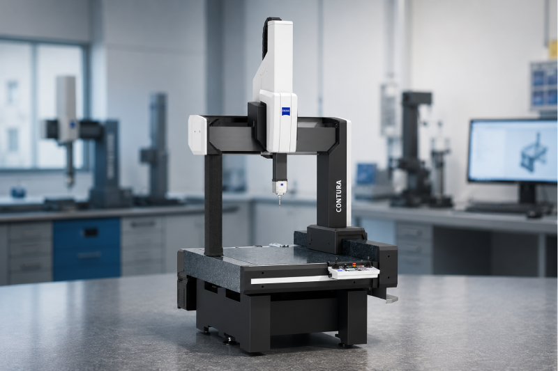
In today’s tooling industry, a difference of just a few microns can determine whether a component performs flawlessly or ends up as costly scrap. Whether you’re manufacturing cutting tools, molds, dies, punches, or precision machined parts, maintaining consistent dimensional accuracy is no longer optional—it’s a competitive advantage. Unfortunately, many tooling manufacturers still rely on manual inspection methods or conventional measuring systems that struggle to verify complex contours, radii, and profiles accurately. The result? Increased rework, delayed deliveries, higher rejection rates, and dissatisfied customers. This is where a contour measuring instrument becomes a game-changer. Designed to capture intricate profiles with micron-level precision, it helps manufacturers inspect critical geometries quickly, improve process control, and deliver consistent quality. In this guide, you’ll learn how tooling manufacturers can use a contour measuring instrument to achieve micron-level accuracy, reduce production errors, and strengthen their quality assurance process. Table of Contents Why Micron-Level Accuracy Matters in Tooling Manufacturing What Is a Contour Measuring Instrument? How Does a Contour Measurement Machine Improve Precision? Key Applications in the Tooling Industry Benefits of Using a Contour Measuring Instrument How to Choose the Right Contour Measuring Instrument Conclusion FAQs Why Does Micron-Level Accuracy Matter in Tooling Manufacturing? Tooling components directly influence the quality of every finished product they produce. Even a slight deviation in a mold cavity, punch profile, cutting edge, or die contour can create dimensional inconsistencies throughout an entire production batch. Micron-level accuracy helps manufacturers: Reduce costly rework Improve first-pass yield Maintain tight tolerances Meet customer specifications Increase tool life Ensure repeatable production quality For industries such as automotive, aerospace, electronics, and medical manufacturing, precision isn’t simply preferred—it’s required. What is micron-level accuracy in tooling manufacturing? Micron-level accuracy refers to measuring and controlling dimensions within one thousandth of a millimeter (µm), ensuring tooling components meet extremely tight tolerances required for precision manufacturing. What Is a Contour Measuring Instrument? A contour measuring instrument is a precision metrology solution designed to measure the profile, contour, angle, radius, step height, groove, chamfer, and other complex geometries of manufactured components. Unlike traditional gauges or manual inspection tools, a contour measurement machine traces the surface profile of a component and converts it into highly accurate digital measurement data. This allows quality teams to compare actual measurements against CAD drawings or engineering specifications with exceptional precision. Because it delivers detailed contour analysis, manufacturers gain confidence that every critical profile meets design intent before production moves forward. How Does a Contour Measurement Machine Improve Precision? Many quality issues originate from small profile deviations that manual inspection simply cannot detect. A modern contour measurement machine eliminates this uncertainty through advanced digital measurement capabilities. 1. Detects Tiny Profile Deviations Complex tool profiles often contain microscopic variations that impact performance. Digital contour measurement identifies these deviations before they become production problems. 2. Provides Repeatable Measurements Operator-dependent measurements create inconsistencies. A contour measuring instrument standardizes inspection, ensuring reliable and repeatable results regardless of who performs the measurement. 3. Compares Parts Against CAD Data Instead of relying on visual inspection, manufacturers can compare actual contours with engineering drawings, enabling quick identification of dimensional differences. 4. Speeds Up Quality Inspection Automated measurement routines significantly reduce inspection time while increasing accuracy. This allows quality teams to inspect more parts without sacrificing precision. How Does a Contour Measuring Instrument Reduce Scrap and Rework? Every rejected tool represents wasted machining time, raw material, labor, and production capacity. Using a contour measuring instrument helps manufacturers: Manufacturing Challenge How Contour Measurement Helps Incorrect tool profiles Detects profile deviations early High rejection rates Identifies dimensional errors before dispatch Manual inspection errors Automates precise measurements Frequent rework Enables immediate corrective action Customer complaints Improves product consistency Production delays Speeds up inspection workflows Early detection means defects are corrected before expensive downstream operations occur. Where Are Contour Measuring Instruments Used in the Tooling Industry? A contour measuring instrument supports inspection across a wide range of tooling applications. Common applications include: Tool and die manufacturing Injection mold inspection Progressive dies Punches and dies Cutting tools CNC machined precision components Precision fixtures Automotive tooling Aerospace tooling Medical device tooling Whether measuring intricate radii or complex edge geometries, contour measurement ensures every feature meets specification. Which industries benefit most from contour measuring instruments? Tool & die manufacturing, automotive, aerospace, electronics, medical device manufacturing, mold making, CNC machining, and precision engineering industries benefit significantly from contour measuring instruments because they require micron-level dimensional accuracy. What Are the Biggest Benefits of Using a Contour Measuring Instrument? Investing in advanced contour measurement technology delivers measurable business value beyond inspection alone. Improved Product Quality Consistent measurements ensure every manufactured tool meets customer requirements. Reduced Manufacturing Costs Early defect detection minimizes scrap, rework, and warranty claims. Faster Production Cycles Automated inspection reduces manual measurement time and improves throughput. Better Customer Confidence Delivering consistently accurate components strengthens supplier relationships and long-term business opportunities. Enhanced Process Control Inspection data helps identify machining trends, enabling continuous process improvement. Easier Compliance Accurate measurement records support ISO quality systems and customer audits. How Do You Choose the Right Contour Measuring Instrument? Not every manufacturing environment has identical inspection requirements. When evaluating a contour measuring instrument, consider: Measurement accuracy Vertical and horizontal measuring range CAD comparison capability Automation features Software functionality Reporting options Ease of operation Future scalability Service and technical support A solution that integrates seamlessly into your quality control process provides greater long-term value than simply selecting the lowest-priced option. What should buyers look for before purchasing a contour measurement machine? Buyers should evaluate measurement accuracy, repeatability, software capabilities, CAD comparison, automation features, inspection speed, reporting functionality, application suitability, and long-term service support before selecting a contour measurement machine. Why Is Contour Measurement Becoming Essential for Modern Tooling Manufacturers? As tooling designs become increasingly complex and customer tolerances continue to shrink, conventional inspection methods struggle to keep pace.   Manufacturers are now expected to deliver precision, consistency, and complete measurement traceability. A contour measuring instrument enables manufacturers to achieve these expectations while improving productivity and reducing operational costs. Rather than
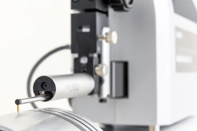
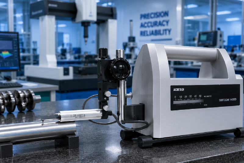
How Surface Roughness Testing Improves Product Quality in Precision Manufacturing

How Surface Roughness Testing Improves Product Quality in Precision Manufacturing

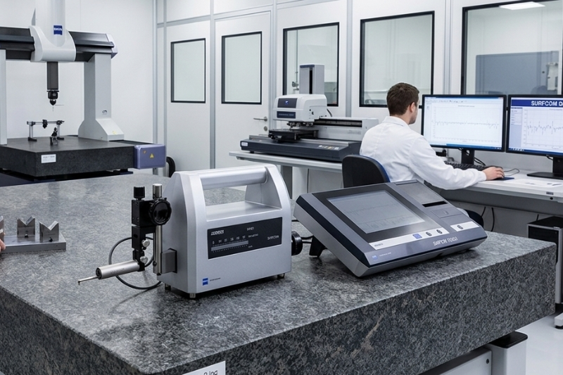
Precision manufacturing leaves no room for guesswork. A component may look flawless to the naked eye, yet microscopic surface imperfections can lead to premature wear, poor sealing, excessive friction, coating failures, or even complete product rejection. This is where a surface roughness tester becomes one of the most valuable tools on the shop floor. Whether you’re machining automotive engine components, aerospace parts, medical devices, or precision tooling, performing a reliable surface roughness test helps ensure every part meets design specifications before it reaches your customer. For manufacturers striving to reduce defects, improve consistency, and comply with global quality standards, investing in the right inspection equipment isn’t just an option—it’s a competitive advantage. In this guide, we’ll explore how surface roughness testing enhances product quality, why it matters in precision manufacturing, and why many quality professionals rely on the ZEISS surface roughness tester for accurate, repeatable measurements. Table of Contents What Is Surface Roughness Testing? Why Surface Finish Matters in Precision Manufacturing How a Surface Roughness Tester Improves Product Quality Industries That Depend on Surface Roughness Testing Why Choose a ZEISS Surface Roughness Tester? How to Select the Right Surface Roughness Tester Frequently Asked Questions Conclusion What Is Surface Roughness Testing? A surface roughness test is a quality inspection process used to measure the microscopic peaks and valleys present on a machined surface. These measurements determine whether a component meets the required finish specified in engineering drawings or international standards. The most commonly evaluated parameters include: Parameter Description Ra Average surface roughness Rz Average maximum peak-to-valley height Rq Root mean square roughness Rt Total height of the surface profile Using a high-precision surface roughness tester, manufacturers can verify these values quickly and accurately, ensuring every component performs as intended. What is the purpose of a surface roughness test? The purpose of a surface roughness test is to measure the texture of a machined surface to ensure it meets quality specifications, improves product performance, reduces wear, and complies with manufacturing standards. Why Does Surface Finish Matter in Precision Manufacturing? A smooth-looking component isn’t always a functional component. Surface finish directly affects how parts interact during operation. Even tiny variations can impact: Component lifespan Friction and wear Lubrication retention Coating adhesion Sealing performance Fatigue resistance Product reliability For example, in automotive engine manufacturing, an improperly finished crankshaft or piston can increase friction, reduce efficiency, and shorten engine life. Detecting these issues before assembly prevents expensive warranty claims and production delays. How Does a Surface Roughness Tester Improve Product Quality? A surface roughness tester does much more than measure numbers—it provides actionable quality insights throughout the manufacturing process. 1. Detects Machining Defects Early Surface imperfections caused by worn cutting tools, improper feeds, vibration, or incorrect machining parameters can be identified before parts move to the next production stage. Early detection reduces: Scrap Rework Material waste Machine downtime 2. Ensures Consistent Product Quality Consistency is one of the biggest challenges in high-volume manufacturing.   Routine surface roughness tests allow quality teams to verify that every batch meets identical specifications, improving customer confidence and reducing inspection failures. 3. Supports International Quality Standards Many industries require compliance with standards such as: ISO ASME JIS A professional surface roughness tester provides traceable measurements that simplify audits and quality documentation. Why is surface roughness important for ISO quality standards? Surface roughness ensures manufactured parts meet defined engineering tolerances, helping organizations comply with ISO quality management requirements while maintaining consistent production quality. 4. Improves Component Performance Surface finish influences how components function under real operating conditions. Examples include: Component Impact of Poor Surface Finish Engine Shafts Increased friction Bearings Faster wear Hydraulic Parts Leakage Gears Noise and vibration Molds Poor product finish By measuring roughness before assembly, manufacturers reduce field failures and improve product durability. 5. Reduces Production Costs Quality inspection is often viewed as an expense. In reality, effective surface roughness testing saves money by reducing: Customer complaints Warranty claims Scrap rates Rework costs Machine adjustments The return on investment is often realized through improved production efficiency and fewer rejected components. Which Industries Depend on Surface Roughness Testing? Nearly every precision manufacturing industry relies on accurate surface measurement. Key sectors include: Automotive OEMs Tier 1 & Tier 2 Automotive Suppliers CNC Machining Companies Aerospace Manufacturers Medical Device Manufacturers Tool & Die Manufacturers Precision Engineering Companies Industrial Equipment Manufacturers For automotive engine component manufacturers, maintaining consistent surface finish is essential for ensuring proper sealing, lubrication, and long-term component reliability. Why Choose a ZEISS Surface Roughness Tester? When accuracy and repeatability matter, measurement equipment becomes just as important as the machining process itself. A ZEISS surface roughness tester is designed for demanding industrial environments where precision cannot be compromised. Key advantages include: High-accuracy surface measurement Portable design for shop-floor inspections Fast measurement and reporting Compliance with ISO, ASME, and JIS standards User-friendly interface Reliable and repeatable results Suitable for a wide range of machined components For manufacturers looking to improve inspection efficiency without sacrificing accuracy, ZEISS offers a dependable solution trusted by quality professionals worldwide. Which surface roughness tester is best for precision manufacturing? A portable ZEISS surface roughness tester is an excellent choice for manufacturers seeking accurate, repeatable measurements, standards compliance, and efficient quality inspections directly on the production floor. How Do You Choose the Right Surface Roughness Tester? Before purchasing a surface roughness tester, consider the following: Measurement Accuracy Choose an instrument capable of measuring the required surface finish parameters with high precision. Industry Standards Ensure compatibility with ISO, ASME, and JIS measurement standards. Portability For shop-floor inspections, portable testers improve productivity and reduce inspection delays. Ease of Use Operators should be able to perform measurements with minimal training. Reporting Capability Look for instruments that generate detailed inspection reports for documentation and quality audits.   Selecting the right equipment helps improve process control while reducing inspection time across production lines. Conclusion In precision manufacturing, quality isn’t achieved by chance—it’s verified through accurate measurement. A reliable surface roughness tester helps manufacturers detect machining issues early, maintain consistent product quality,

How Surface Roughness Testers Improve Engine Component Performance and Manufacturing Quality

How Surface Roughness Testers Improve Engine Component Performance and Manufacturing Quality

Every automotive manufacturer understands one hard truth—an engine is only as reliable as the precision of its components. A tiny imperfection on the surface of a crankshaft, camshaft, piston, or cylinder bore can lead to excessive friction, faster wear, oil leakage, and even premature engine failure. These aren’t just quality issues; they’re expensive problems that impact customer satisfaction, warranty costs, and brand reputation. This is where a surface roughness tester becomes an essential quality control tool. By accurately measuring the surface finish of critical engine parts, manufacturers can detect machining inconsistencies before components move to assembly. The result is improved performance, longer component life, and consistent manufacturing quality. In this blog, you’ll learn how surface roughness testing enhances engine component performance, why it is becoming indispensable for automotive manufacturers, and how selecting the right measurement solution can help reduce defects while improving production efficiency. Table of Contents Why Surface Finish Matters in Engine Manufacturing What Is a Surface Roughness Tester? How Surface Roughness Impacts Engine Performance Which Engine Components Require Surface Roughness Testing? Benefits of Surface Roughness Testing in Automotive Manufacturing Choosing the Right Surface Roughness Tester Frequently Asked Questions Conclusion   Why Does Surface Finish Matter in Engine Manufacturing? Surface finish is much more than how smooth a component looks. It directly affects how engine parts interact under high temperatures, heavy loads, and continuous movement. For example, a crankshaft journal with excessive roughness creates higher friction against bearings. Similarly, an overly smooth cylinder bore may fail to retain sufficient lubrication, reducing engine efficiency and accelerating wear. A proper surface roughness test helps manufacturers ensure every machined component meets the specified roughness values before assembly. Poor Surface Finish Can Lead To: Increased friction and heat generation Premature component wear Poor lubrication retention Leakage in sealing surfaces Reduced fuel efficiency Higher warranty claims Increased production rejections For automotive OEMs and Tier 1 suppliers, maintaining precise surface finish is no longer optional—it’s a competitive advantage.   What Is a Surface Roughness Tester? A surface roughness tester is a precision metrology instrument used to measure the microscopic peaks and valleys present on a machined surface. It provides numerical values such as Ra, Rz, and other roughness parameters that determine whether a component meets engineering specifications. Instead of relying on visual inspection or operator judgment, manufacturers use these instruments to make data-driven quality decisions. Modern surface roughness testers offer: High-precision roughness measurement Portable and bench-top options Digital reporting Fast inspection cycles Compliance with international quality standards Easy integration into quality control workflows Whether inspecting engine blocks, camshafts, pistons, gears, or bearing surfaces, accurate roughness measurement ensures every component performs as intended. How Does Surface Roughness Affect Engine Component Performance? Even microscopic variations in surface texture can significantly impact engine reliability. The table below highlights how surface finish influences different automotive engine components. Engine Component Importance of Surface Roughness Impact of Poor Surface Finish Crankshaft Reduces friction with bearings Excessive wear and bearing failure Camshaft Ensures smooth valve operation Increased friction and noise Cylinder Bore Retains lubrication Oil consumption and reduced efficiency Pistons Improves sealing performance Blow-by and power loss Valve Seats Creates effective sealing Compression leakage Bearings Minimizes contact stress Shorter bearing life A controlled surface finish helps manufacturers produce engines that are quieter, more fuel-efficient, and capable of lasting hundreds of thousands of kilometers. How Do Surface Roughness Testers Help Detect Manufacturing Problems Early? One of the biggest advantages of using a surface roughness tester is identifying machining issues before parts reach assembly. Instead of discovering defects after engine testing—or worse, after delivery—manufacturers can detect issues immediately following machining operations. Common defects identified include: Tool wear marks Excessive machining chatter Grinding burns Surface waviness Burr formation Incorrect cutting parameters Inconsistent finishing processes Early detection reduces scrap, minimizes rework, and improves production consistency across every manufacturing batch. What is the primary purpose of a surface roughness tester in automotive manufacturing? The primary purpose of a surface roughness tester is to measure the surface finish of precision-machined automotive components, ensuring they meet required specifications for friction control, lubrication retention, sealing performance, durability, and overall engine reliability. Why are automotive manufacturers investing more in surface roughness testing? Automotive manufacturers are investing in advanced surface roughness testing because it helps improve engine efficiency, reduce warranty claims, support zero-defect manufacturing, meet international quality standards, and ensure consistent production quality across high-volume manufacturing lines. Which Engine Components Require Surface Roughness Testing? Not every engine component has the same surface finish requirements, but every critical contact surface must meet strict roughness specifications. Even a slight variation in Ra or Rz values can affect lubrication, sealing, heat dissipation, and wear resistance. Below are some of the most critical automotive components where routine surface roughness testing is essential. Engine Component Why Surface Roughness Matters Manufacturing Benefit Crankshaft Journals Reduces friction between journals and bearings Longer bearing life Camshafts Ensures smooth valve timing and operation Improved engine efficiency Cylinder Bores Retains lubricating oil while minimizing wear Better fuel economy Pistons Improves ring sealing performance Reduced blow-by Connecting Rods Maintains dimensional accuracy Increased durability Valve Seats Provides leak-proof sealing Better combustion efficiency Bearings Prevents premature wear Longer service life Engine Blocks Ensures proper mating with cylinder heads Reduced coolant and oil leakage For manufacturers supplying Automotive OEMs and Tier 1 companies, verifying the surface finish of these components before assembly helps prevent costly production delays and field failures. How Does Surface Roughness Testing Improve Manufacturing Quality? Quality isn’t built during final inspection—it starts with every machining operation. A surface roughness test provides measurable data that helps production teams identify process variations before they become expensive quality issues. Here’s how manufacturers benefit: 1. Reduces Scrap and Rework Machining inconsistencies often go unnoticed until assembly or final inspection. Surface roughness measurements reveal defects immediately, allowing operators to correct tooling or machining parameters before producing additional defective parts. 2. Improves Tool Life Management A gradual increase in surface roughness often signals cutting tool wear. Monitoring roughness values helps maintenance teams replace tools at the right time

How In-Line Machine Vision Systems Improve PCB Assembly Quality and Defect Detection in Electronics Manufacturing

How In-Line Machine Vision Systems Improve PCB Assembly Quality and Defect Detection in Electronics Manufacturing

Introduction A single missing component, a poor solder joint, or an incorrect part placement can turn a perfectly designed PCB into a costly failure. In today’s fast-paced electronics manufacturing environment, even the smallest defect can lead to product recalls, customer complaints, production delays, and increased rework costs. As production volumes continue to rise and electronic assemblies become more complex, manual inspection is no longer enough. Manufacturers need a faster, smarter, and more reliable way to inspect every PCB without slowing down production. This is where an in-line machine vision system becomes a game-changer. By combining high-speed cameras, intelligent image processing, and real-time inspection capabilities, a machine vision system helps manufacturers detect defects instantly, improve PCB assembly quality, and achieve consistent production standards. In this blog, you’ll learn how in-line machine vision inspection works, why it’s becoming essential for electronics manufacturing, and how it helps reduce defects while increasing productivity and profitability. Table of Contents What Is an In-Line Machine Vision System? Why PCB Assembly Inspection Is Critical How Does a Machine Vision System Work? Common PCB Defects Detected by Vision Systems Benefits of In-Line Machine Vision Systems Manual Inspection vs Machine Vision Inspection Choosing the Right Vision System for PCB Manufacturing Conclusion FAQs What Is an In-Line Machine Vision System? An in-line machine vision system is an automated inspection solution installed directly within a production line to inspect every PCB during manufacturing without interrupting production. Using industrial cameras, intelligent software, lighting technology, and image processing algorithms, the system captures high-resolution images and compares them against predefined quality standards to identify defects instantly. Unlike manual visual inspection, a vision system machine delivers consistent, objective, and repeatable inspection results regardless of operator fatigue or production speed. What does a machine vision system do in PCB manufacturing? A machine vision system automatically inspects printed circuit boards by identifying assembly defects such as missing components, incorrect polarity, soldering issues, misalignment, damaged parts, and labeling errors before products move to the next production stage. Why Is PCB Assembly Inspection So Important? PCB assemblies contain hundreds—or even thousands—of tiny components. A single defect can affect the performance of the entire electronic device. Without automated inspection, manufacturers often experience: Increased product failures Higher rework and repair costs Customer returns Warranty claims Production bottlenecks Compliance issues Modern electronics manufacturers cannot afford these risks, especially in industries such as automotive electronics, medical devices, aerospace, telecommunications, and semiconductor manufacturing. How Does an In-Line Machine Vision System Improve PCB Assembly Quality? An in-line vision system continuously monitors every PCB as it moves through the production line. 1. Detects Missing Components The system instantly identifies missing ICs, resistors, capacitors, connectors, or other electronic components before the board proceeds further. 2. Verifies Component Placement Even slight component misalignment can lead to functional failures. A machine vision system checks position, orientation, and placement accuracy within milliseconds. 3. Identifies Solder Defects Poor solder joints are among the leading causes of PCB failures. The system detects: Insufficient solder Excess solder Solder bridges Cold solder joints Open connections 4. Confirms Polarity and Orientation Incorrect orientation of polarized components such as diodes, electrolytic capacitors, LEDs, and ICs is automatically detected before shipment. 5. Reads Labels and Markings Integrated OCR and barcode verification ensure every PCB meets traceability requirements while reducing manual verification time. Why are manufacturers replacing manual PCB inspection with machine vision systems? Manufacturers are adopting machine vision systems because they deliver faster inspections, higher accuracy, reduced labor costs, better traceability, and consistent quality compared to manual inspection. Common PCB Defects a Machine Vision System Can Detect Defect Type Inspection Benefit Missing Components Prevents incomplete assemblies Wrong Component Placement Improves assembly accuracy Component Polarity Errors Reduces functional failures Solder Bridges Prevents electrical shorts Insufficient Solder Improves product reliability Bent Pins Detects assembly damage PCB Surface Damage Improves product appearance Barcode & Label Errors Supports complete traceability What Are the Business Benefits of Using a Machine Vision System? Beyond quality inspection, an in-line machine vision system delivers measurable business value. Higher First-Pass Yield Detecting defects early prevents defective boards from moving further into production. Reduced Rework and Scrap Early defect detection significantly lowers repair costs and material waste. Faster Production Automated inspection keeps pace with high-speed SMT production lines without creating bottlenecks. Improved Product Quality Consistent inspection improves customer satisfaction and reduces field failures. Lower Operating Costs Although automation requires an initial investment, manufacturers often achieve substantial long-term savings by reducing labor costs, warranty claims, and production downtime. Better Traceability Every inspection result can be digitally stored, supporting quality audits and regulatory compliance. Manual Inspection vs Machine Vision System Feature Manual Inspection Machine Vision System Inspection Speed Slow High-Speed Accuracy Operator Dependent Highly Consistent Fatigue High None Repeatability Variable Excellent Real-Time Inspection Limited Yes Data Collection Manual Automatic Production Downtime Higher Lower Quality Consistency Moderate Excellent How Do You Choose the Right Vision System for PCB Manufacturing? Not every vision system machine is suitable for every production line. When selecting a solution, consider: Camera resolution Inspection speed AI-based defect detection Lighting technology Integration with SMT production lines PLC compatibility Barcode and OCR capability Custom inspection algorithms Ease of maintenance Scalability for future production A scalable machine vision system ensures your investment continues to deliver value as production requirements evolve. What industries benefit most from machine vision systems? Machine vision systems are widely used in PCB manufacturing, Electronics Manufacturing Services (EMS), semiconductor production, automotive electronics, medical devices, industrial electronics, aerospace, telecommunications, and consumer electronics manufacturing. Why Electronics Manufacturers Are Investing in Automated Vision Systems Global electronics manufacturers are under constant pressure to deliver flawless products while reducing production costs. An advanced vision system enables manufacturers to: Improve quality consistency Increase production throughput Reduce inspection time Minimize human error Support Industry 4.0 initiatives Build smarter manufacturing operations As PCB complexity continues to increase, automated inspection is quickly becoming a necessity rather than a competitive advantage. Conclusion Quality is no longer inspected at the end of production—it is built into every stage of the manufacturing process. An in-line machine vision

How XRF Analyzers Help Jewellery Manufacturers Verify Gold Purity Without Damaging Products

How XRF Analyzers Help Jewellery Manufacturers Verify Gold Purity Without Damaging Products

Gold purity is the foundation of trust in the jewellery industry. Whether you’re manufacturing bridal jewellery, refining precious metals, exporting ornaments, or operating a hallmarking centre, even a small error in purity verification can lead to financial losses, customer disputes, and reputational damage. Traditional gold testing methods have served the industry for decades, but many of them require scratching, cutting, or using chemicals that can alter or damage valuable products. As customer expectations and quality standards continue to rise, jewellery manufacturers need a faster, more accurate, and non-destructive solution. This is where XRF analyzers are transforming quality control. With instant elemental analysis and zero damage to the product, these advanced instruments help manufacturers verify gold purity confidently while improving operational efficiency. In this guide, you’ll discover how portable XRF technology works, why leading jewellery manufacturers are adopting it, and how it can improve your production and quality assurance processes. Table of Contents What Are XRF Analyzers? Why Is Gold Purity Verification Important? How Do Portable XRF Analyzers Work? Benefits of Using Portable XRF Analyzers in Jewellery Manufacturing Traditional Gold Testing vs Portable XRF Analysis Applications Across the Jewellery & Precious Metals Industry How to Choose the Right Portable XRF Analyzer Frequently Asked Questions Conclusion What Are XRF Analyzers? XRF analyzers are advanced material analysis instruments that use X-ray fluorescence technology to determine the elemental composition of metals without cutting, scratching, or damaging the sample. For jewellery manufacturers, these analyzers quickly identify the percentage of: Gold (Au) Silver (Ag) Platinum (Pt) Palladium (Pd) Copper (Cu) Nickel (Ni) Zinc (Zn) Other alloying elements Within just a few seconds, operators receive highly accurate purity results, making the inspection process significantly faster than conventional methods. What is an XRF analyzer used for in jewellery manufacturing? An XRF analyzer is used to verify gold purity, identify alloy composition, detect counterfeit jewellery, inspect incoming raw materials, and ensure consistent product quality without damaging the jewellery. Why Is Gold Purity Verification So Critical? Gold jewellery is sold based on trust. A slight variation in purity can impact pricing, hallmark certification, export compliance, and customer confidence. For manufacturers handling hundreds or thousands of jewellery pieces daily, manual testing methods simply cannot keep pace. Some common challenges include: Counterfeit or mixed alloys Incorrect alloy composition Supplier inconsistencies Hallmark compliance issues Production quality variations Costly product rejections Using portable XRF analyzers helps eliminate these risks by providing reliable results before products move to the next production stage. How Do Portable XRF Analyzers Work? A portable XRF spectrometer directs low-energy X-rays onto the jewellery surface. Each metal emits a unique fluorescent signature that the analyzer measures and converts into an accurate elemental composition report. The entire inspection process typically takes less than 10 seconds. The process is simple: Step Process 1 Place jewellery under the analyzer 2 Start the measurement 3 X-rays excite metal atoms 4 Detector measures fluorescence 5 Software displays purity percentages instantly Unlike acid testing or destructive methods, no sample preparation is required. Can portable XRF analyzers detect fake gold? Yes. Portable XRF analyzers accurately identify gold content and detect metals commonly used in counterfeit jewellery, helping manufacturers and buyers verify authenticity instantly. How Do Handheld XRF Analyzers Improve Jewellery Manufacturing? Modern handheld XRF analyzers have become an essential quality control tool because they combine speed, precision, and portability. 1. Non-Destructive Testing Every jewellery piece remains completely intact. No scratches. No cutting. No chemical damage. This is especially valuable when inspecting finished ornaments or luxury jewellery collections. 2. Instant Purity Results Instead of waiting for laboratory reports, manufacturers receive accurate purity analysis within seconds. This significantly improves production speed. 3. Higher Quality Control Consistent alloy composition leads to: Better product consistency Fewer customer complaints Reduced manufacturing defects Improved hallmark compliance 4. Lower Testing Costs Traditional testing often requires consumables, chemicals, or laboratory processing. A handheld XRF machine minimizes recurring testing expenses while increasing productivity. 5. Better Supplier Verification Incoming gold bars, casting materials, recycled metals, and purchased alloys can all be verified before entering production. This prevents expensive material-related issues later in manufacturing. Traditional Gold Testing vs Portable XRF Analysis Feature Traditional Testing Portable XRF Analyzers Product Damage Yes No Testing Time Several minutes to hours Seconds Chemical Usage Yes No Sample Preparation Required Not Required Portability Limited High Real-Time Results No Yes Multiple Element Detection Limited Yes For manufacturers producing large volumes, portable XRF technology offers a clear operational advantage. Where Are Portable XRF Analyzers Used in the Jewellery Industry? Today’s portable XRF analyzers are widely used across multiple business operations. Jewellery Manufacturing Gold purity verification Alloy composition analysis Production quality inspection Hallmarking Centres Pre-certification testing Compliance verification Precious Metal Refining Incoming material inspection Purity confirmation Bullion Trading Gold bar authentication Coin verification Assay Laboratories Elemental composition analysis Material certification Jewellery Export Houses Export quality compliance Customer-specific purity verification How to Choose the Right XRF Analyzer for Your Business If you’re planning to invest in a new analyzer, consider these factors: High accuracy across precious metals Fast measurement speed Easy-to-use software Portable and lightweight design Low maintenance requirements Reliable after-sales service Calibration support Trusted XRF spectrometer suppliers India Choosing the right supplier ensures long-term performance, technical support, and maximum return on investment. Which industries benefit most from portable XRF analyzers? Portable XRF analyzers are widely used in jewellery manufacturing, precious metal refining, hallmarking centres, bullion trading, recycling facilities, assay laboratories, mining, metal fabrication, and quality inspection industries. Why More Jewellery Manufacturers Are Switching to XRF Technology As production volumes increase and quality expectations become stricter, manufacturers cannot rely solely on traditional testing methods. Portable XRF technology helps businesses: Improve customer trust Increase production efficiency Reduce inspection costs Minimize human error Meet international quality standards Strengthen supplier quality management More importantly, it enables manufacturers to inspect every product confidently without risking damage to valuable jewellery. Conclusion Accuracy, speed, and product safety have become essential in today’s jewellery manufacturing industry. Modern XRF analyzers provide a practical solution for verifying gold purity without scratching, cutting, or chemically altering valuable

Why Weld Penetration Inspection Is Critical for Structural Steel Fabrication in Infrastructure Projects

Why Weld Penetration Inspection Is Critical for Structural Steel Fabrication in Infrastructure Projects

Imagine investing months into fabricating structural steel for a bridge, metro station, or industrial facility, only to discover during final inspection that several critical welds have inadequate weld penetration. The result? Costly rework, project delays, increased inspection expenses, and, in the worst cases, compromised structural integrity. For structural steel manufacturers and EPC contractors, weld quality is far more than a production requirement—it’s a commitment to safety, compliance, and long-term performance. Every weld contributes to the strength of the finished structure, and even a small defect can have significant consequences. This is where weld penetration inspection becomes essential. Accurate inspection helps manufacturers verify that every welded joint meets design specifications before components leave the fabrication shop or reach the construction site. In this article, you’ll learn why weld penetration inspection is critical for infrastructure projects, how it improves quality control, reduces project risks, and why modern digital inspection systems are replacing traditional manual inspection methods. Table of Contents What Is Weld Penetration? Why Is Weld Penetration Important in Structural Steel Fabrication? What Problems Are Caused by Poor Welding Penetration? How Does Weld Penetration Inspection Improve Infrastructure Quality? Manual vs Digital Weld Inspection How to Choose the Right Weld Inspection System Conclusion FAQs What Is Weld Penetration? Weld penetration refers to the depth at which molten weld metal fuses into the base material during welding. Proper penetration ensures the welded joint can withstand design loads, environmental stress, and years of continuous service. In simple terms, deeper and uniform welding penetration creates stronger, safer, and more reliable welded joints. For industries like infrastructure construction, structural steel fabrication, bridge manufacturing, and heavy engineering, achieving the correct penetration welding profile is a mandatory quality requirement rather than an optional improvement. What is weld penetration in welding? Weld penetration is the depth of fusion between the weld metal and the parent metal. Adequate penetration ensures strong, durable, and defect-free welded joints that meet engineering and safety standards. Why Is Weld Penetration Important in Structural Steel Fabrication? Every infrastructure project depends on thousands of welded connections. Whether it’s a flyover, airport terminal, metro rail, warehouse, or industrial plant, structural steel carries enormous loads throughout its service life. If weld penetration is inconsistent, the entire structure may become vulnerable to: Premature fatigue failure Reduced load-bearing capacity Cracks under cyclic loading Poor corrosion resistance Structural instability Increased maintenance costs For QA/QC managers, these risks translate into failed inspections, rejected components, expensive repairs, and delayed project completion. Proper weld inspection ensures these issues are identified before fabricated components reach the installation stage. Why Buyers Prioritize Weld Penetration Inspection Business Challenge Impact on Infrastructure Projects Benefit of Weld Inspection Incomplete penetration Weak structural joints Ensures full fusion verification Rework costs Increased fabrication expenses Detects defects early Project delays Missed construction timelines Faster inspection process Compliance failures Failed audits and certifications Supports quality documentation Safety risks Potential structural failures Improves long-term reliability What Problems Are Caused by Poor Welding Penetration? Many fabrication defects remain hidden until final inspection—or worse, until the structure is already in service. Poor welding penetration often results from incorrect welding parameters, improper joint preparation, unsuitable filler materials, or inconsistent operator techniques. Common problems include: Lack of Fusion The weld metal fails to bond completely with the base metal, reducing joint strength. Root Defects Insufficient penetration at the root creates weak points that may crack under load. Reduced Fatigue Strength Infrastructure components experience continuous stress from wind, traffic, vibration, and temperature changes. Inadequate penetration accelerates fatigue failure. Increased Rework Reworking structural welds requires additional manpower, material, inspection, and production time, directly affecting project profitability. Compliance Issues Infrastructure projects often require strict adherence to welding codes and client specifications. Poor penetration can lead to inspection failures and rejected assemblies. Why is weld penetration critical for infrastructure projects? Because infrastructure structures must withstand heavy loads, environmental conditions, and decades of service. Proper weld penetration ensures stronger joints, improved safety, regulatory compliance, and reduced maintenance costs. How Does Weld Penetration Inspection Improve Infrastructure Quality? Modern fabrication facilities are moving beyond subjective visual inspections toward digital measurement systems that provide repeatable and highly accurate results. Instead of relying solely on operator judgment, advanced weld inspection solutions measure penetration characteristics with precision and generate standardized inspection reports. The benefits extend across every stage of fabrication. 1. Improves Quality Consistency Digital inspection minimizes human error and delivers consistent measurements across multiple operators and production batches. 2. Reduces Rework Costs Detecting insufficient penetration early prevents defective components from moving further along the production process, saving both time and material costs. 3. Enhances Client Confidence Accurate inspection records demonstrate that fabricated components meet contractual quality requirements, increasing customer trust and improving project acceptance rates. 4. Supports Regulatory Compliance Infrastructure projects often require documented evidence of weld quality. Digital inspection systems simplify reporting and make audits easier. 5. Accelerates Production Fast, repeatable inspections reduce bottlenecks in quality control, allowing fabrication teams to maintain production schedules without compromising accuracy. How does weld penetration inspection reduce project costs? By identifying welding defects before fabrication is complete, inspection prevents costly repairs, minimizes material waste, reduces production delays, and lowers overall quality assurance expenses. Manual vs Digital Weld Inspection: Which Is Better? For decades, many fabrication shops relied on manual gauges, visual checks, and operator experience to assess weld quality. While these methods are still used for basic inspections, they often lack the precision, repeatability, and documentation required for today’s large-scale infrastructure projects. As construction standards become more stringent and clients demand greater traceability, digital weld inspection systems are becoming the preferred choice. Inspection Parameter Manual Inspection Digital Weld Inspection Measurement Accuracy Operator-dependent High precision and repeatable Inspection Speed Moderate Fast and efficient Data Recording Manual documentation Automatic digital reports Human Error Higher Significantly reduced Compliance Support Limited Excellent documentation for audits Production Efficiency Lower Higher productivity For QA/QC managers handling hundreds or even thousands of welded joints, digital inspection offers measurable advantages. Instead of relying on subjective judgment, inspectors can verify weld penetration with confidence and maintain consistent quality across

How to Choose the Right Coating Thickness Gauge for Accurate Industrial Inspection (2026 Buying Guide)

How to Choose the Right Coating Thickness Gauge for Accurate Industrial Inspection (2026 Buying Guide)

Choosing the right coating thickness gauge is more important than many manufacturers realize. Whether you’re inspecting painted automotive components, powder-coated metal parts, galvanized steel, or protective coatings on industrial equipment, accurate coating thickness measurement directly impacts product quality, durability, and compliance. A coating that is too thin may fail to protect the surface from corrosion, while one that is too thick can lead to cracking, peeling, increased material costs, and production delays. That’s why selecting the right coating thickness gauge isn’t simply about buying a measuring instrument—it’s about investing in consistent quality and long-term performance. Today’s industries demand precision, traceability, and compliance with international standards. Modern coating thickness gauges provide quick, reliable, and non-destructive measurements that help quality control teams maintain production consistency while reducing costly rework. However, with multiple measurement technologies, features, and specifications available, selecting the right instrument can be confusing. This guide explains everything you need to know before purchasing a coating thickness gauge, including how they work, the different measurement technologies available, key buying considerations, industry applications, international standards, and expert tips to help you make the right investment. What Is a Coating Thickness Gauge? A coating thickness gauge is a precision measuring instrument used to determine the thickness of coatings applied to various substrates. These coatings may include paint, powder coating, electroplating, galvanizing, anodizing, enamel, plastic coatings, and other protective finishes. Depending on the substrate and application, coating thickness gauges use different measurement technologies to provide fast, accurate, and repeatable results without damaging the coated surface. These instruments play a critical role in industrial quality assurance because they verify whether the applied coating meets the required specifications. Accurate measurements help manufacturers maintain product consistency, improve durability, reduce waste, and comply with international quality standards. In many industries, coating thickness gauges are also referred to as dry film thickness (DFT) meters or coating thickness testers. Why Accurate Coating Thickness Measurement Matters? The thickness of a protective coating determines how effectively it performs throughout the product’s life cycle. Even small variations can significantly impact durability and performance. A coating that is too thin may expose the base material to moisture, chemicals, abrasion, or corrosion. This often results in premature failure, increased maintenance costs, and reduced product life. Conversely, applying excessive coating thickness increases material consumption, production costs, and drying time while potentially causing cracking, blistering, or adhesion problems. Accurate coating thickness measurement also supports compliance with customer specifications and international standards such as ISO and ASTM. Manufacturers can reduce warranty claims, improve product reliability, and ensure every component meets inspection requirements before shipment. Types of Coating Thickness Gauges Different industries require different measurement technologies depending on the substrate material and coating type. Magnetic Induction Gauges Magnetic induction gauges measure non-magnetic coatings on ferrous metals such as steel and iron. They are widely used for measuring paint, epoxy coatings, powder coatings, and galvanized layers. This technology offers fast, accurate, and non-destructive measurements, making it ideal for manufacturing, fabrication, and automotive inspection. Eddy Current Gauges Eddy current coating thickness gauges are designed for measuring non-conductive coatings on non-ferrous conductive metals, including aluminum, copper, brass, and certain grades of stainless steel. These gauges are commonly used in aerospace, automotive, electronics, and aluminum fabrication industries where lightweight materials require precise coating control. Ultrasonic Coating Thickness Gauges Ultrasonic coating thickness gauges use high-frequency sound waves to measure coating thickness on both metallic and non-metallic substrates. Unlike magnetic or eddy current gauges, ultrasonic technology is suitable for plastics, composites, fiberglass, wood, and concrete. It is often used in industries where coatings are applied to materials that cannot be measured using conventional magnetic methods. Key Factors to Consider Before Buying Choosing the right coating thickness gauge requires more than comparing prices. Understanding your inspection requirements helps ensure the instrument delivers reliable performance over the long term. The first factor to consider is the base material. Magnetic induction gauges are ideal for ferrous metals, while eddy current gauges are designed for non-ferrous conductive materials. If your inspection involves plastics, composites, or other non-metallic substrates, ultrasonic technology is generally the better choice. Next, evaluate the type of coating being measured. Different coatings such as paint, powder coating, anodizing, chrome plating, galvanizing, or thermal spray may require different measurement capabilities. Confirm that the instrument supports the coating and substrate combination used in your production process. Measurement range is another important consideration. Some applications require only thin coating measurements, while others involve thicker protective layers. Choosing a gauge with an appropriate measuring range ensures accurate readings across all products. Accuracy and repeatability are equally important. High-precision industries such as aerospace, automotive, semiconductor manufacturing, and medical device production demand extremely accurate measurements. Investing in a high-quality instrument minimizes inspection errors and improves customer confidence. Surface condition should also be considered. Rough surfaces, curved components, and small parts may require specialized probes or measurement modes to maintain accuracy. Calibration is another essential aspect. Instruments that support certified calibration standards and quick field calibration help maintain measurement reliability while simplifying quality audits. Modern coating thickness gauges also include digital features such as memory storage, USB connectivity, Bluetooth communication, statistical analysis, inspection reporting, and software integration. These capabilities improve traceability, simplify documentation, and support Industry 4.0 quality management systems. Finally, portability matters. Lightweight handheld gauges with long battery life allow inspectors to perform measurements efficiently both in production facilities and on-site installations. Industry Applications Coating thickness measurement is essential across numerous industrial sectors. The automotive industry uses coating thickness gauges to inspect vehicle body panels, painted components, electroplated parts, and corrosion-resistant coatings. Consistent measurements ensure high-quality finishes while protecting vehicles against environmental damage. In aerospace manufacturing, precise coating thickness helps maintain structural integrity while meeting stringent safety and regulatory requirements. Every protective coating must fall within specified tolerances to ensure long-term performance. Manufacturing companies rely on coating thickness gauges for quality control during production. From fabricated metal components to industrial machinery, accurate measurements help maintain consistency and reduce rework. Powder coating manufacturers use these instruments to verify uniform coating thickness before

Coordinate Measuring Machine (CMM) Complete Guide to Precision Inspection, Types, Applications & Buying Tips

Coordinate Measuring Machine (CMM): Complete Guide to Precision Inspection, Types, Applications & Buying Tips

When precision determines product quality, even the smallest measurement error can lead to rejected parts, production delays, and increased manufacturing costs. Whether you’re producing automotive components, aerospace parts, medical devices, or precision molds, maintaining dimensional accuracy isn’t optional—it’s essential. That’s where a coordinate measuring machine comes into play. Instead of relying on manual inspection methods that are time-consuming and prone to human error, manufacturers use CMMs to verify dimensions with exceptional precision and consistency. In this guide, you’ll learn everything about the coordinate measuring machine, including how it works, different types of CMMs, their applications across industries, key benefits, buying considerations, and maintenance tips. If you’re planning to invest in a CMM machine, this guide will help you make an informed decision. Table of Contents What is a Coordinate Measuring Machine? How Does a Coordinate Measuring Machine Work? Types of Coordinate Measuring Machines What is CMM Inspection? Industries That Use CMM Machines Benefits of Using a Coordinate Measuring Machine How to Choose the Right CMM Machine Maintenance Tips Future Trends in Coordinate Measurement Frequently Asked Questions Conclusion Meta Description Call-to-Action What is a Coordinate Measuring Machine? A coordinate measuring machine (CMM) is a precision inspection system used to measure the physical geometry of manufactured components. It accurately captures the X, Y, and Z coordinates of a part to verify whether it meets design specifications. A CMM coordinate measuring machine uses touch probes or non-contact laser scanners to inspect dimensions, profiles, hole positions, angles, flatness, roundness, and geometric tolerances with micron-level accuracy. Unlike traditional measuring tools such as calipers or micrometers, a CMM provides automated, repeatable, and highly accurate measurements, making it a critical part of modern quality control. How Does a Coordinate Measuring Machine Work? A coordinate measuring machine operates by moving a probe or scanning sensor across a workpiece. The machine records thousands of coordinate points and compares them with the original CAD model or engineering drawing. The inspection process typically includes: Positioning the component securely. Creating or importing the inspection program. Probing or scanning the surface. Collecting measurement data. Comparing actual dimensions with CAD specifications. Generating an inspection report. This automated workflow minimizes inspection errors while improving productivity and traceability. What Are the Types of Coordinate Measuring Machines? Choosing the right CMM machine depends on the size of your components, inspection speed, required accuracy, and production environment. 1. Bridge Coordinate Measuring Machine Bridge CMMs are the most commonly used systems in precision manufacturing. Best For Automotive components Precision machining Electronics General manufacturing Advantages Excellent accuracy Stable structure Ideal for medium-sized components 2. Horizontal Arm CMM Horizontal arm CMMs are designed for inspecting large and bulky workpieces. Common Applications Automotive body panels Aircraft structures Heavy machinery Advantages Easy loading Large measuring range Suitable for oversized parts 3. Cantilever CMM Cantilever CMMs provide easy access to the measuring area from three sides. Ideal For Small precision parts Tool rooms Laboratories Benefits Compact design Fast measurement Excellent accessibility 4. Portable Coordinate Measuring Machine Portable CMMs allow inspection directly on the production floor. These systems eliminate the need to transport heavy components to a dedicated inspection room. Best For Large assemblies On-site inspection Reverse engineering 5. Articulated Arm CMM An articulated arm CMM combines portability with flexibility. The operator manually moves the arm while the machine records accurate coordinate data. Advantages Easy to operate Portable Flexible measurement angles 6. Laser Scanner CMM Modern coordinate measuring machines increasingly integrate laser scanning technology. Instead of touching the surface, laser scanners rapidly collect millions of measurement points. Advantages Extremely fast inspection High-density point cloud Suitable for complex surfaces Excellent for reverse engineering What is CMM Software? The hardware is only one part of a modern inspection system. Advanced CMM software controls measurement routines, analyzes collected data, compares results with CAD models, and generates detailed inspection reports. Popular software capabilities include: CAD comparison GD&T evaluation SPC analysis Automated reporting Reverse engineering support Digital inspection workflows Powerful software significantly improves inspection speed while reducing manual programming time. What is CMM Inspection? CMM inspection is the process of verifying manufactured parts using a coordinate measuring machine to ensure they meet engineering specifications. During inspection, the machine checks: Dimensions Hole locations Flatness Perpendicularity Circularity Surface profiles Position tolerances Geometric tolerances This ensures every component satisfies quality standards before reaching customers. Which Industries Use Coordinate Measuring Machines? Automotive Industry Automotive manufacturers rely on CMMs to inspect engine blocks, gears, transmission parts, chassis components, and body panels. Benefits include: Improved assembly accuracy Lower rejection rates Consistent product quality Aerospace Industry Aircraft components require extremely tight tolerances. Coordinate measuring machines help inspect: Turbine blades Engine components Landing gear Structural assemblies Even microscopic deviations can impact safety, making precision inspection essential. Medical Industry Medical device manufacturers use CMMs to inspect implants, surgical instruments, orthopedic components, and precision medical equipment. High accuracy ensures compliance with stringent regulatory standards. Energy Industry Power generation industries inspect turbines, valves, pumps, and precision-machined parts using CMM technology to improve reliability and operational efficiency. Die & Mold Industry Toolmakers use coordinate measuring machines to validate molds and dies before production. Accurate inspection minimizes costly rework and improves mold life What Are the Benefits of Using a Coordinate Measuring Machine? Investing in a coordinate measuring machine offers several advantages: Exceptional measurement accuracy Faster inspection cycles Reduced human error Automated quality control Improved production efficiency Better product consistency Reduced scrap and rework Complete digital inspection reports Increased customer confidence Long-term cost savings Modern manufacturers view a CMM not as an expense but as an investment in quality assurance. How to Choose the Right Coordinate Measuring Machine Selecting the right system depends on your manufacturing requirements. Consider the following factors: Component Size Choose a measuring volume suitable for your largest parts. Required Accuracy Higher precision applications require machines with tighter tolerances. Measurement Speed High-volume production often benefits from automated scanning systems. Probe Technology Select between touch probes, optical sensors, or laser scanners based on application. Software Compatibility Ensure compatibility with CAD files and reporting requirements. Automation Needs Consider robotic loading and

Contour Measuring Machine Buying Guide How to Choose the Right System for High-Precision Inspection

Contour Measuring Machine Buying Guide: How to Choose the Right System for High-Precision Inspection

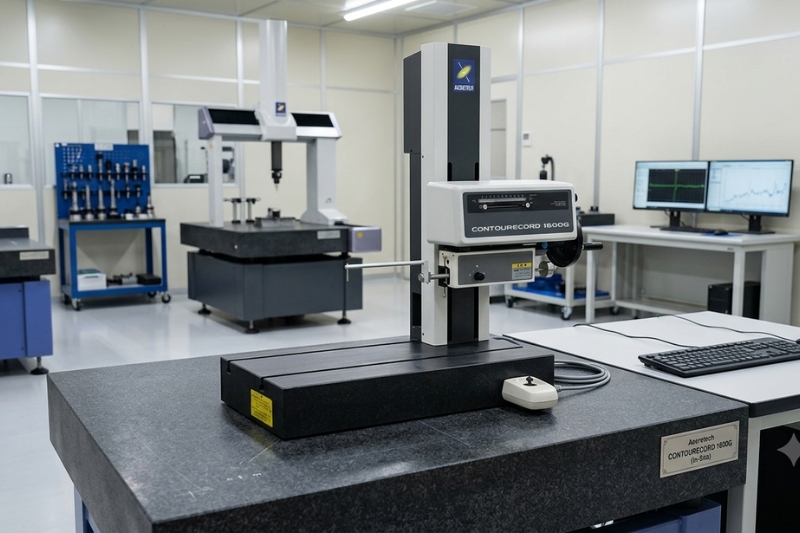
Looking for the Right Contour Measuring Machine? Here’s What You Need to Know Choosing the right contour measuring machine isn’t just about buying another piece of inspection equipment—it’s about investing in product quality, manufacturing efficiency, and customer confidence. Imagine spending hours machining a precision component only to discover it fails quality inspection because of an unnoticed contour deviation. The result? Production delays, material waste, unhappy customers, and increased costs. That’s exactly why manufacturers across automotive, electronics, aerospace, medical, and precision engineering industries rely on advanced contour measurement systems. This buying guide explains everything you need to know—from how a contour measuring machine works to the features that truly matter—so you can confidently choose a system that matches your inspection requirements. Table of Contents What is a Contour Measuring Machine? How Does a Contour Measuring Machine Work? Industries That Use Contour Measurement 2D vs 3D Contour Measurement Contour Measurement vs Profile Measurement Key Features to Look For How to Choose the Right Contour Measuring Machine Understanding ROI Before Buying Frequently Asked Questions Conclusion What is a Contour Measuring Machine? A contour measuring machine is a precision inspection system designed to measure the shape, geometry, angles, radii, grooves, edges, and contours of manufactured components with extremely high accuracy. Also known as a Contour Measurement Machine or Contour Measuring Instrument, it captures the exact profile of a workpiece using a precision stylus that traces its surface. The collected data is then analyzed through specialized software to compare the actual dimensions with design specifications. In simple terms, it helps manufacturers answer one important question: “Does this part match the engineering drawing?” That answer can make the difference between delivering a perfect product or an expensive rejection. How Does a Contour Measuring Machine Work? The working principle is surprisingly straightforward. Step 1: Position the Component The workpiece is securely placed on the measuring table. Step 2: Stylus Scanning A highly sensitive probe moves across the component’s surface, recording every contour, edge, groove, radius, and angle. Step 3: Data Collection Thousands of measurement points are captured within seconds. Step 4: Software Analysis Advanced software converts the measured data into a detailed contour profile, compares it against CAD drawings or tolerances, and instantly generates inspection reports. This process minimizes operator error while significantly improving inspection consistency. What Industries Use Contour Measuring Machines? Contour inspection has become essential wherever dimensional accuracy directly impacts product performance. Automotive Industry Automotive manufacturers inspect: Engine components Transmission parts Camshafts Pistons Brake systems Gear profiles Accurate contour measurement ensures better assembly and longer product life. Bearings Industry Bearing manufacturers use contour measuring instruments to verify: Raceway profiles Groove geometry Radius measurements Surface transitions Even microscopic contour errors can reduce bearing lifespan. Medical Components Medical devices demand extremely tight tolerances. Contour measuring systems inspect: Surgical tools Dental implants Orthopedic implants Precision medical components Consistent measurement helps manufacturers meet strict regulatory standards. Plastic Parts Manufacturing Injection molded parts often require contour verification for: Snap fits Sealing surfaces Mold geometry Functional edges Contour inspection helps reduce assembly issues before products reach customers. Optical Components Manufacturers producing optical assemblies use contour measurement to inspect: Lens holders Precision housings Alignment features Mechanical interfaces Accurate contour data improves overall optical performance. 2D vs 3D Contour Measurement: Which One Should You Choose? Choosing between 2D and 3D inspection depends entirely on your application. 2D Contour Measurement Best for: Cross-sectional profiles Grooves Angles Radii Simple geometries Advantages: Faster inspections Lower investment Easier programming High repeatability 3D Contour Measurement Ideal for: Complex geometries Freeform surfaces Multi-axis components Advanced engineering parts Advantages: Complete dimensional analysis Better visualization Suitable for highly complex products If your production mainly involves standard machined components, a high-quality 2D contour measuring machine often delivers excellent value. Contour Measurement vs Profile Measurement These terms are often used interchangeably, but they serve different purposes. Contour Measurement Profile Measurement Measures complete geometry Measures surface texture or line profile Evaluates angles, radii, grooves Evaluates surface characteristics Used for dimensional inspection Used for finish evaluation Focuses on shape accuracy Focuses on surface quality Many modern systems combine both capabilities, allowing manufacturers to perform multiple inspections using a single machine. What Features Should You Look for in a Contour Measuring Machine? Not every machine offers the same capabilities. Before making your investment, evaluate these critical features. 1. Measurement Accuracy High accuracy is the foundation of reliable inspection. Look for systems that offer: High-resolution sensors Excellent repeatability Stable mechanical construction Certified calibration standards The more accurate the machine, the fewer quality issues you’ll encounter. 2. Intelligent Software Powerful software simplifies inspection. Choose software that provides: CAD comparison Automatic measurement programs Easy report generation Statistical analysis Data export options User-friendly interface Good software saves operators valuable inspection time. 3. Automation Capabilities As production grows, manual inspection becomes a bottleneck. Modern contour measuring machines support: CNC automation Automatic measurement routines Batch inspections Reduced operator dependency Automation increases productivity while improving consistency. 4. Measurement Speed Inspection should never slow production. A faster contour measuring instrument allows manufacturers to: Inspect more components Reduce downtime Improve production flow Increase throughput Speed becomes especially valuable in high-volume manufacturing. How to Choose the Right Contour Measuring Machine Before purchasing, ask yourself these practical questions. What components will you inspect? Large components require longer measuring ranges, while miniature parts demand higher precision. What level of accuracy do you need? Industries like aerospace and medical manufacturing require tighter tolerances than general machining. Will your inspection needs grow? Buying a scalable system today can eliminate expensive upgrades tomorrow. Is the software easy to use? Complex software increases training time and slows inspections. Does the supplier provide support? Reliable installation, training, calibration, and after-sales service are just as important as machine specifications. Choosing the right partner often matters as much as choosing the right machine. Is a Contour Measuring Machine Worth the Investment? Absolutely. While the initial investment may seem significant, the long-term returns are substantial. A quality contour measuring machine helps manufacturers: Reduce product rejection Improve first-pass quality Minimize material waste Lower rework costs Increase

Surface Roughness Tester Complete Guide to Surface Finish Measurement for Precision Manufacturing (2026)

Surface Roughness Tester: Complete Guide to Surface Finish Measurement for Precision Manufacturing (2026)

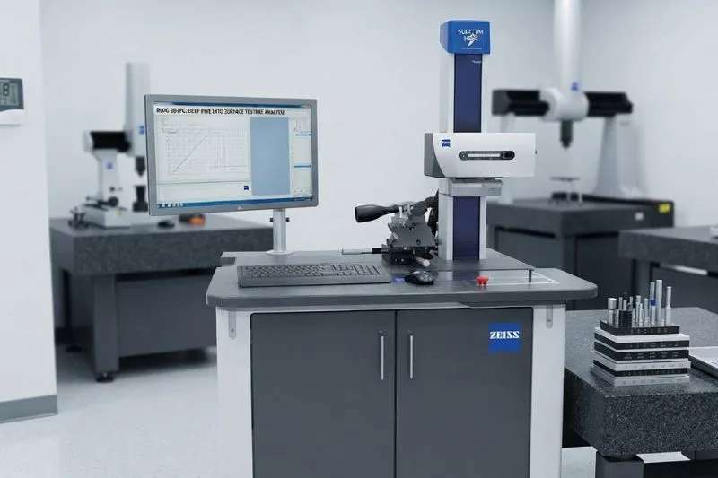
A tiny imperfection on a component’s surface can lead to product failure, rejected batches, unexpected downtime, or costly customer complaints. In industries like semiconductor manufacturing, electronics, automotive, and aerospace, surface quality isn’t just a specification—it’s a critical quality parameter. That’s where a Surface Roughness Tester becomes essential. It helps manufacturers measure, verify, and maintain consistent surface finishes that directly impact performance, durability, and product reliability. Whether you’re a quality control manager looking to reduce inspection errors or a production head planning to automate your inspection process, this guide explains everything you need to know about surface roughness testing, how it works, and how to choose the right solution for your manufacturing environment. Table of Contents Why Surface Roughness Matters What is a Surface Roughness Tester? How Does Surface Roughness Measurement Work? Types of Surface Roughness Testers Portable vs. Bench-Type Surface Roughness Testers Understanding Ra, Rz, and Rq ISO Standards for Surface Roughness Testing Applications Across Industries How to Select the Right Surface Roughness Tester Common Surface Roughness Measurement Mistakes Frequently Asked Questions Conclusion Why Does Surface Roughness Matter? Every machined component may appear smooth to the naked eye, but microscopic peaks and valleys exist on every surface. These tiny irregularities influence: Product performance Wear resistance Friction Sealing capability Coating adhesion Fatigue life Corrosion resistance In semiconductor and electronics manufacturing, even a slight deviation in surface finish can affect component assembly, electrical performance, and long-term reliability. A reliable surface roughness test helps manufacturers detect these imperfections before products reach customers, reducing defects and improving production consistency. What is a Surface Roughness Tester? A Surface Roughness Tester is a precision metrology instrument used to measure the texture of a material’s surface. It evaluates microscopic surface irregularities and converts them into measurable values that help manufacturers verify whether a component meets design specifications. Modern systems can measure parameters such as: Ra Rz Rq Rt Rmax How Does Surface Roughness Measurement Work? A surface roughness tester typically uses a highly sensitive stylus that moves across the surface of a component. Here’s how the process works: Step 1: Stylus Contact The diamond-tipped probe gently travels across the workpiece. Step 2: Profile Detection The stylus records microscopic peaks and valleys. Step 3: Digital Analysis Software converts the collected profile into numerical roughness parameters. Step 4: Inspection Report The system generates an inspection report that can be compared against ISO standards and customer specifications. Today’s advanced systems provide fast measurements, automatic data logging, and seamless integration with quality management software, significantly reducing manual inspection time. What Are the Types of Surface Roughness Testers? Choosing the right instrument depends on production volume, part size, and inspection requirements. Portable Surface Roughness Tester Best suited for: Shop floor inspections Large workpieces On-site quality checks Maintenance applications Benefits: Lightweight Easy to operate Fast measurements Portable and flexible Bench-Type Surface Roughness Tester Ideal for: Laboratory environments High-precision inspection Semiconductor manufacturing Electronics production Medical device manufacturing Benefits: Higher measurement accuracy Advanced analysis Greater repeatability Automated inspection capability Portable vs. Bench-Type Surface Roughness Tester Feature Portable Bench-Type Mobility Excellent Fixed Accuracy Good Very High Automation Limited Excellent Inspection Speed Fast Very Fast Ideal Use Shop Floor Quality Lab Best For Maintenance Precision Manufacturing Manufacturers focused on high-volume production often choose automated bench-type systems to improve consistency and reduce operator dependency. What Are Ra, Rz, and Rq? Understanding these surface roughness parameters is essential for selecting the right inspection criteria. Ra (Average Roughness) Ra is the arithmetic average of all surface deviations from the center line. It is the most commonly specified surface finish parameter across manufacturing industries. Rz (Average Maximum Height) Rz measures the average height difference between the highest peaks and deepest valleys over multiple sampling lengths. It provides a clearer picture of severe surface irregularities. Rq (Root Mean Square Roughness) Rq calculates the root mean square of profile deviations, making it more sensitive to larger surface variations than Ra. It is commonly used in precision engineering and semiconductor applications. Which ISO Standards Apply to Surface Roughness Testing? To ensure consistent inspection worldwide, manufacturers follow internationally recognized standards. Common standards include: ISO 4287 ISO 4288 ISO 21920 ISO 3274 Following ISO standards helps manufacturers: Meet customer requirements Improve quality consistency Simplify audits Ensure global compliance Which Industries Use Surface Roughness Testers? Semiconductor & Electronics Surface finish directly impacts: Wafer processing PCB manufacturing Connector reliability Precision assemblies High-accuracy inspection minimizes microscopic defects and improves production yield. Automotive Manufacturing Surface roughness affects: Engine components Bearings Transmission parts Brake systems Proper inspection improves wear resistance and component life. Aerospace Aircraft components require exceptionally tight tolerances. Surface roughness testing ensures: Fatigue resistance Better aerodynamics Reliable sealing Safety compliance Medical Devices Medical implants and surgical instruments require highly controlled surface finishes to improve: Biocompatibility Sterility Performance Patient safety Tool & Die Manufacturing Precision cutting tools perform better when surface finishes remain within specification, improving machining quality and extending tool life. How Do You Select the Right Surface Roughness Tester? Choosing the right system involves more than comparing specifications. Consider these factors: Measurement Accuracy Higher precision ensures reliable inspection results. Automation Capability Automated systems reduce inspection time and improve repeatability. Software Integration Look for systems that integrate with your quality management software and workflow. Production Volume High-volume manufacturing benefits from automated inspection solutions. Standards Compliance Ensure the equipment supports current ISO measurement standards. Service & Support Reliable technical support and calibration services reduce downtime and protect your investment. Common Surface Roughness Measurement Mistakes Even experienced manufacturers make avoidable mistakes. Avoid these common issues: Using an incorrect cutoff length Measuring contaminated surfaces Skipping regular calibration Using worn stylus tips Ignoring environmental vibration Incorrect parameter selection (Ra vs. Rz) Poor operator training Preventing these errors improves measurement consistency and reduces unnecessary product rejection. Conclusion As manufacturing tolerances become tighter in 2026, accurate surface inspection is no longer optional. A reliable Surface Roughness Tester helps manufacturers improve quality, reduce defects, maintain compliance, and build greater customer confidence. For semiconductor, electronics, automotive, aerospace, and medical manufacturers, investing in advanced surface measurement technology

Scroll to Top