QS Metrology | Portable XRF Analyser | Portable XRF Spectrometer | Optical Emission spectrometer | XRD | Surface roughness Tester | roughness measuring machine | Portable Roughness Tester | Contour measuring machine | Contour Tester | Coordinate measuring machine | 3 D Coordinate measuring machine | Weld penetration inspection | Weld penetration measurement System | Stereomicroscope | Coating thickness tester | Video Measuring machine | Metallurgical Image analysis | Metallurgical microscope

admin

How Automated Coordinate Measuring Machine Solutions Enhance Quality Control in Semiconductor Production Lines

How Automated Coordinate Measuring Machine Solutions Enhance Quality Control in Semiconductor Production Lines

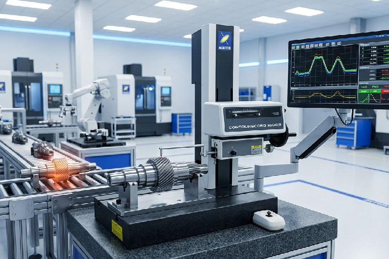
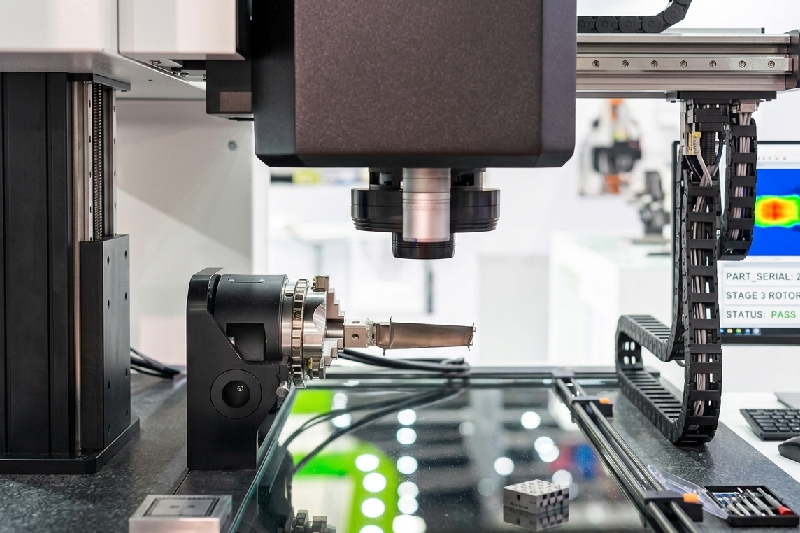
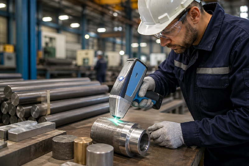
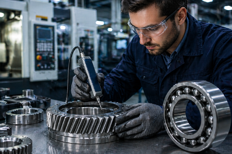
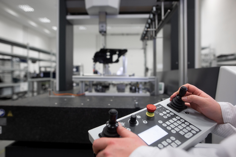
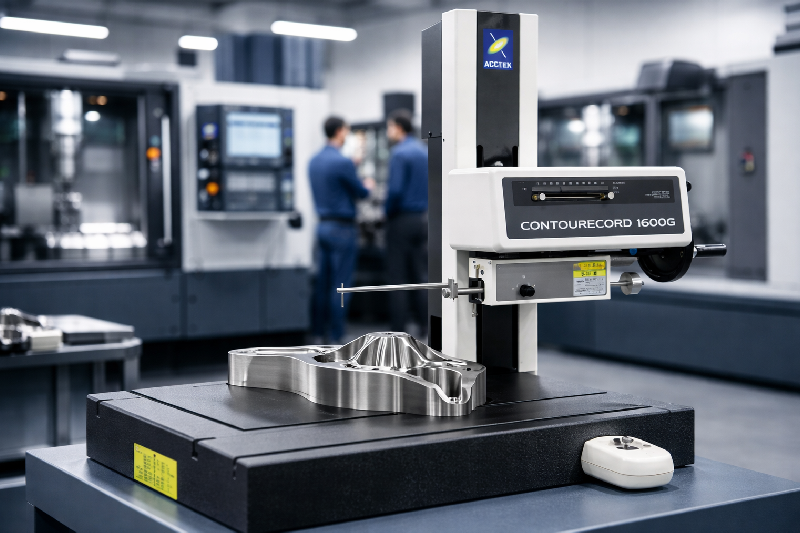
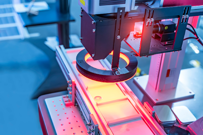
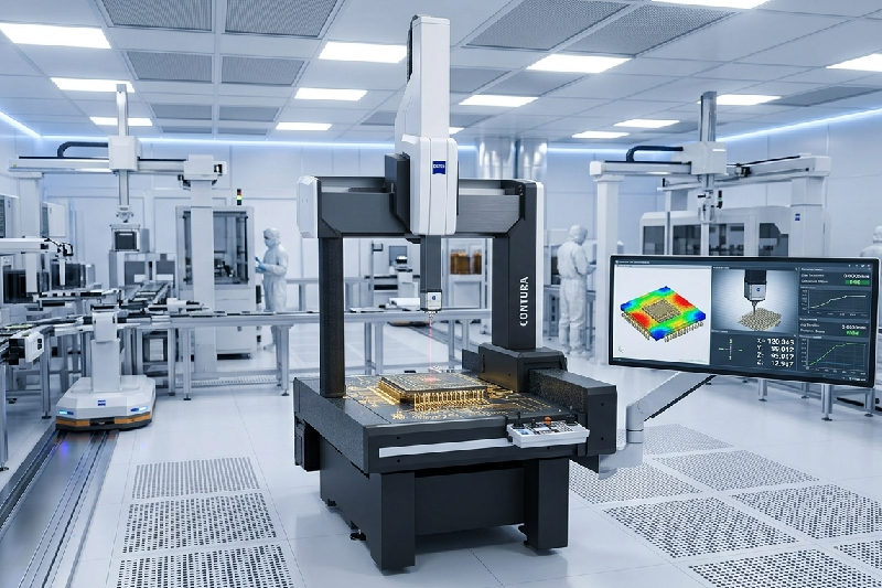
Introduction: The Hidden Cost of Tiny Errors In semiconductor manufacturing, even a micron-level deviation can turn into a costly batch rejection. If you’re a quality control manager or production head, you already know the pressure—tight tolerances, faster production cycles, and zero room for error. But here’s the real challenge: manual inspection methods and outdated measurement tools simply can’t keep up anymore. This is where a coordinate measuring machine (CMM) changes the game. More importantly, automated CMM solutions are now helping semiconductor manufacturers achieve unmatched accuracy, speed, and consistency. In this blog, you’ll discover how automated CMM systems improve quality control, reduce defects, and drive real ROI in semiconductor production lines. Table of Contents What is a Coordinate Measuring Machine (CMM)? Why Quality Control is Critical in Semiconductor Manufacturing How Automated CMM Solutions Work Key Benefits of Automated CMM in Semiconductor Production What Features to Look for in a CMM Machine How to Choose the Right CMM for Your Facility FAQs What is a Coordinate Measuring Machine (CMM)? A coordinate measuring machine (CMM) is a high-precision device used to measure the physical geometrical characteristics of a component. It uses probes or sensors to capture exact dimensions, ensuring every part meets strict design specifications. In semiconductor manufacturing, where components are incredibly small and complex, CMM measurement ensures precision down to microns—or even sub-micron levels. Whether it’s wafer inspection, PCB components, or micro-electronic parts, a CMM measuring machine ensures every detail is accurate, repeatable, and compliant with quality standards. Why Quality Control is Critical in Semiconductor Manufacturing? Semiconductor production is unforgiving. A small defect can lead to complete product failure, customer dissatisfaction, or regulatory issues. Here’s what most manufacturers struggle with: Increasing miniaturization of components Tight tolerance requirements High production volumes Pressure to reduce rejection rates Traditional inspection methods often fall short because they are slower, prone to human error, and lack consistency. That’s why many manufacturers are shifting toward automated coordinate machine solutions—to keep up with speed without compromising accuracy. How Automated CMM Solutions Work in Production Lines? Automated CMM coordinate measuring machine systems integrate directly into your production workflow. Instead of manual intervention, these machines perform measurements automatically using programmed routines. Here’s how it typically works: Parts are loaded onto the CMM system (manually or via robotic arms) The system runs pre-programmed inspection sequences Sensors or probes capture precise measurements Data is analyzed in real-time Deviations are flagged instantly This automation allows continuous inspection without slowing down production, which is critical in semiconductor environments. How Automated CMM Solutions Improve Quality Control? 1. How Automation Eliminates Human Error Manual inspection always carries variability. Even experienced operators can make mistakes under pressure. Automated CMM machines remove this risk by standardizing measurement processes. Every component is inspected using the same parameters, ensuring consistency across batches. This leads to: More reliable results Reduced rework Higher confidence in quality reports 2. How CMM Measurement Improves Accuracy at Micro Levels Semiconductor components require ultra-precise measurements. A slight deviation can affect performance or functionality. Automated CMM measurement systems provide: Sub-micron accuracy Repeatable results High-resolution data capture This level of precision is something traditional tools simply cannot achieve consistently. 3. How Automated CMM Reduces Defects and Waste One of the biggest advantages of automation is early defect detection. Instead of discovering issues at the end of production, CMM measuring machines identify deviations in real-time. This helps you: Fix problems early in the process Reduce material wastage Lower rejection rates In high-volume semiconductor production, this translates directly into cost savings. 4. How Real-Time Data Improves Decision Making Modern coordinate measuring machine systems don’t just measure—they provide actionable insights. With integrated software, you can: Monitor trends Identify recurring issues Optimize production parameters This transforms quality control from a reactive process into a proactive strategy. 5. How Automation Boosts Production Speed Speed is critical in semiconductor manufacturing. Manual inspection slows everything down. Automated CMM machines work continuously without fatigue, enabling: Faster inspection cycles Increased throughput Reduced bottlenecks This ensures your production line runs smoothly without compromising quality. What Features to Look for in a CMM Machine? Choosing the right CMM machine is crucial for maximizing ROI. Here are key features to consider: High accuracy and repeatability for micro components Automation compatibility with robotic systems Advanced software for data analysis Flexible probe systems for complex geometries Scalability for future production needs Many buyers also compare options like zeiss cmm machine, but it’s important to evaluate based on your specific production requirements rather than brand alone. How to Choose the Right Coordinate Measuring Machine? Before investing in a coordinate measuring machine, ask these critical questions: What level of accuracy do your components require? What is your production volume? Do you need inline or offline inspection? What is your budget and expected ROI? Also, consider the CMM machine price not just as a cost—but as a long-term investment. A well-chosen system can significantly reduce defects, improve efficiency, and increase profitability. Real-World Impact: Why Manufacturers Are Switching to Automated CMM Many semiconductor manufacturers have already made the shift—and the results are impressive: Up to 40% reduction in inspection time Significant drop in rejection rates Improved compliance with quality standards Better customer satisfaction This isn’t just a trend—it’s becoming the industry standard. Conclusion: Precision, Speed, and Control—All in One System If you’re still relying on manual inspection or outdated tools, you’re likely losing time, money, and efficiency. Automated coordinate measuring machine solutions bring together accuracy, speed, and intelligence, making them essential for modern semiconductor production lines. From reducing defects to improving decision-making, the benefits go far beyond measurement—they transform your entire quality control process. FAQs What is a coordinate measuring machine used for? A coordinate measuring machine (CMM) is used to measure the physical dimensions of components with high precision, ensuring they meet design specifications. How does a CMM machine improve quality control? A CMM machine improves quality by providing accurate, repeatable measurements and detecting defects early in the production process. What industries use CMM measuring machines? Industries like semiconductor manufacturing, electronics, automotive, and aerospace widely

Contour Measurement Machine Price vs ROI A Guide for Precision Manufacturers

Contour Measurement Machine Price vs ROI: A Guide for Precision Manufacturers

Let’s be honest—no plant manager likes spending lakhs on a new machine unless the returns are crystal clear. And when it comes to a contour measurement machine, the first question is always: “Is this really worth the investment?” In high-speed steel manufacturing, even a tiny profile deviation can lead to batch rejection, rework, or worse—customer complaints. Traditional inspection methods simply can’t keep up anymore. This is where a modern contour measuring machine or contour tracer steps in. In this guide, we’ll break down the real cost vs ROI of investing in a contour measuring instrument—so you can make a confident, data-backed decision for your plant. Table of Contents What is a Contour Measurement Machine? Why Steel Manufacturers Struggle Without It? Contour Measurement Machine Price: What You’re Really Paying For? ROI Breakdown: How It Pays You Back? Real Benefits for High-Speed Production Lines How to Choose the Right Contour Machine? Conclusion FAQs What is a Contour Measurement Machine? A contour measurement machine (also known as a contour tracer or contour measuring instrument) is used to measure the profile and geometry of components with extreme precision. It captures surface contours, edges, radii, angles, and complex shapes that are critical in steel and precision machining. Unlike manual gauges or basic measuring tools, a contour tracer machine gives you: High-resolution profile analysis Repeatable and consistent results Digital reports for quality audits Integration with automated inspection systems For steel manufacturers dealing with high volumes and tight tolerances, this isn’t just a measuring tool—it’s a quality control backbone. Why Steel Manufacturers Struggle Without a Contour Measuring Machine? If you’re still relying on manual inspection or outdated tools, you’ve probably faced these issues: Inconsistent measurements across shifts High rejection rates due to profile mismatch Delays in quality approval Difficulty maintaining international standards Here’s the truth: manual inspection works—until production scales. In high-speed environments, even a small delay or error multiplies quickly. Without a reliable contour instrument, you’re not just risking quality—you’re losing money every day through: Scrap material Rework costs Production downtime Customer dissatisfaction Contour Measurement Machine Price: What You’re Really Paying For When evaluating the price of a contour measuring machine, most buyers focus only on the upfront cost. But that’s just one part of the equation. What Influences the Price? The cost of a contour machine depends on: Measurement accuracy and resolution Automation level (manual vs CNC) Software capabilities Brand and technology (e.g., advanced systems like ZEISS contour measuring machines) Integration with existing production lines A high-end contour tracer might seem expensive initially, but it often includes advanced analytics, automation, and long-term reliability. Typical Investment Range While prices vary, industrial-grade contour measuring instruments typically fall into: Entry-level systems: Basic profile measurement Mid-range systems: Enhanced accuracy and software High-end systems: Fully automated, Industry 4.0-ready But here’s the key insight—price alone doesn’t determine value. ROI does. ROI Breakdown: How a Contour Measurement Machine Pays You Back Let’s shift the focus from cost to returns. Because this is where most decision-makers change their perspective. 1. Reduced Rejection Rates Even a 1–2% reduction in rejection can save lakhs annually in steel manufacturing. A contour measuring instrument ensures every profile is within tolerance before it moves forward. 2. Faster Inspection Cycles Manual inspection can’t match the speed of a contour tracer machine. Automated measurement reduces inspection time drastically, keeping up with high-speed production lines. 3. Lower Rework Costs Incorrect profiles caught late mean rework or scrap. With real-time contour measurement, errors are detected early—saving both time and material. 4. Improved Process Control A contour measurement machine gives you data, not guesses. This helps in: Process optimization Root cause analysis Continuous improvement 5. Better Customer Trust & Compliance Accurate digital reports make audits easier and build confidence with clients—especially in industries like automotive and aerospace. Real Benefits for High-Speed Production Lines Let’s bring this into your day-to-day operations. Imagine running a steel plant where thousands of components move every hour. Without automated inspection, quality checks become a bottleneck. With a contour machine, you get: Inline or near-line inspection capability Real-time feedback for operators Consistent quality across batches Reduced dependency on skilled manual inspectors Key Benefits at a Glance: Higher first-pass yield Reduced downtime Faster production cycles Data-driven decision-making This isn’t just about measurement—it’s about transforming your entire quality process. How to Choose the Right Contour Measuring Machine? Not all machines are built the same. Choosing the right one depends on your production needs. Ask These Questions Before Buying: What level of accuracy do I need? Will this integrate with my current production line? Do I need automation or manual operation? What software features are included? Is the system scalable for future growth? Pro Tip: If you’re handling complex profiles or high volumes, investing in an advanced system like a ZEISS contour measuring machine can deliver higher long-term ROI due to its precision and reliability. Value-Driven Insights for Decision Makers If you’re still on the fence, here’s a simple way to evaluate your ROI: Calculate Your Losses Today: Monthly rejection cost Rework expenses Downtime due to inspection delays Now compare that with the cost of a contour tracer machine. In most cases, manufacturers recover their investment within 6–18 months—sometimes even faster. That’s the difference between seeing it as a cost… and recognizing it as a profit-driving asset. Conclusion A contour measurement machine isn’t just another piece of equipment—it’s a strategic investment in quality, efficiency, and profitability. For steel manufacturers dealing with high-speed production and strict tolerances, the real question isn’t “Can we afford it?” It’s “Can we afford not to have it?” When you look beyond the price and focus on ROI, the answer becomes clear. FAQs What is a contour measurement machine used for? A contour measurement machine is used to measure the profile, shape, and geometry of components with high precision, ensuring they meet design specifications. How much does a contour measuring machine cost? The cost varies depending on accuracy, automation, and features, ranging from entry-level to high-end industrial systems. What is the ROI of a contour measuring instrument?

Why Machine Vision Systems are Critical for High-Speed Steel Rod Inspection in Metal Grading Applications

Why Machine Vision Systems are Critical for High-Speed Steel Rod Inspection in Metal Grading Applications?

In a high-speed steel manufacturing line, there’s no room for guesswork. When steel rods are moving at lightning speed, even a tiny defect or incorrect metal grading can lead to costly rework, rejected batches, or worse—customer complaints and compliance issues.Many quality heads and plant managers still rely on manual inspection or outdated systems that simply can’t keep up. The result? Inconsistent grading, human error, and missed defects. This is exactly where a machine vision system becomes a game-changer. In this blog, we’ll break down why adopting a machine vision system for in-line inspection is no longer optional—but critical—for achieving accuracy, speed, and consistency in metal grading applications. Table of Contents What is a Machine Vision System? Why Traditional Inspection Fails in High-Speed Steel Production How Machine Vision Transforms Steel Rod Inspection Key Benefits for Metal Grading Applications Real-World Impact on Steel Manufacturers How to Choose the Right Vision System Machine Conclusion FAQs What is a Machine Vision System? A machine vision system is an advanced inspection technology that uses cameras, sensors, and intelligent software to automatically inspect, measure, and analyze products on a production line. In steel rod manufacturing, a vision system machine captures high-speed images of rods and evaluates: Surface defects (cracks, scratches, pits) Dimensional accuracy Surface finish consistency Color or texture variations (for grading) Unlike human inspection, machine vision doesn’t get tired, distracted, or inconsistent. It delivers precise, repeatable results—every single time. Why Traditional Inspection Fails in High-Speed Steel Production? Let’s be honest—manual inspection was never designed for today’s production speeds. When steel rods move at high velocity, inspectors face multiple challenges: Limited reaction time to identify defects Fatigue leading to missed errors Inconsistent judgment across shifts Inability to detect micro-level defects Even conventional inspection systems struggle because they lack real-time processing and adaptability. This creates a dangerous gap between production speed and inspection capability. And in metal grading applications, this gap directly impacts: Product quality Customer trust Regulatory compliance Operational efficiency How Machine Vision System Transforms Steel Rod Inspection? Real-Time, High-Speed Inspection A machine vision system operates at the same speed as your production line—sometimes even faster. It captures and processes images in milliseconds, ensuring no rod goes unchecked. Intelligent Defect Detection Modern machine vision systems use AI-driven algorithms to detect even the smallest defects that are invisible to the human eye. This includes: Micro cracks Surface irregularities Rolling defects Inclusion marks Automated Metal Grading The system doesn’t just detect defects—it classifies rods based on predefined grading standards. This ensures: Consistent grading across batches Elimination of subjective decisions Standardized output quality Seamless Integration with Production Lines A well-designed vision system machine integrates directly into your existing production setup, enabling: Automated rejection systems Real-time alerts Data tracking and reporting Key Benefits of Machine Vision in Metal Grading Applications 1. Unmatched Accuracy and Consistency A machine vision system eliminates human error and ensures every rod is inspected using the same criteria.No bias. No fatigue. Just precision. 2. Increased Production Efficiency By automating inspection, manufacturers can: Reduce bottlenecks Maintain high-speed operations Minimize downtime This directly improves throughput without compromising quality. 3. Reduced Scrap and Rework Early defect detection means problems are caught before they escalate. This helps in: Lowering rejection rates Reducing material waste Saving operational costs 4. Data-Driven Decision Making Modern machine vision systems generate valuable insights, such as: Defect patterns Process inefficiencies Quality trends This data empowers plant managers to optimize processes and improve output quality. 5. Compliance and Quality Assurance Consistent metal grading is critical for meeting industry standards. A vision system ensures: Traceability Documentation Audit readiness Real-World Impact on Steel Manufacturers Steel manufacturers who have implemented machine vision systems report significant improvements: Up to 90% reduction in inspection errors Faster grading processes Improved customer satisfaction Stronger brand reputation More importantly, they gain confidence in their production quality—something that’s hard to achieve with manual methods. How to Choose the Right Vision System Machine? Not all systems are created equal. Choosing the right vision system machine is crucial for success.Here are key factors to consider: Speed Compatibility Ensure the system can handle your production line speed without lag. Detection Capabilities Look for systems that can identify both surface and dimensional defects. AI and Automation Features Advanced machine vision systems offer smarter detection and continuous learning. Integration Flexibility Ensure the system can handle your production line speed withoThe system should easily integrate with your existing setup.ut lag. Scalability Choose a solution that grows with your production needs. Pro Tips for Maximum ROI If you’re investing in a machine vision system, maximize its impact by: Training your team for better adoption Regularly updating inspection parameters Using data insights for process optimization Partnering with experienced solution providers Conclusion In today’s fast-paced steel manufacturing environment, relying on manual inspection is like trying to win a race on foot while others are using high-speed machines.A machine vision system bridges the gap between speed and accuracy—ensuring every steel rod meets the highest standards of quality and gradingFor quality heads and plant managers, this isn’t just about technology. It’s about control, consistency, and confidence in every batch you produce. FAQs What is a machine vision system used for in steel manufacturing? A machine vision system is used for real-time inspection of steel rods to detect defects, measure dimensions, and ensure accurate metal grading. Can machine vision systems work at high production speeds? Yes, modern machine vision systems are designed to operate at high speeds, making them ideal for in-line inspection. How does machine vision improve metal grading accuracy? It uses predefined algorithms and AI to ensure consistent, unbiased grading without human error. Is machine vision suitable for existing production lines? Absolutely. Most vision system machines can be integrated into existing setups with minimal disruption. A machine vision system is used for real-time inspection of steel rods to detect defects, measure dimensions, and ensure accurate metal grading.Yes, modern machine vision systems are designed to operate at high speeds, making them ideal for in-line inspection.It uses predefined algorithms and AI to ensure consistent, unbiased grading without

Role of Coating Thickness Gauges in Automotive Paint Shops & Surface Finishing Units

Role of Coating Thickness Gauges in Automotive Paint Shops & Surface Finishing Units

In an automotive paint shop, even a tiny mistake in coating thickness can turn into a big problem—rust complaints, failed audits, or rejected batches. If you’ve ever dealt with inconsistent finishes or customer returns, you already know how frustrating (and expensive) that can be. This is exactly where a coating thickness gauge becomes more than just a tool—it becomes your quality safeguard. Whether you’re a QA manager trying to meet OEM standards, a production head aiming to reduce rework, or a paint shop supervisor handling daily output pressure, the right measurement approach can change everything. In this blog, we’ll break down how coating thickness gauges (including DFT meters, thickness gauge paint tools, and coating thickness testers) play a critical role in automotive paint shops—and how they directly impact quality, cost, and efficiency. Table of Contents Why Coating Thickness Matters in Automotive Industry What is a Coating Thickness Gauge? Role of Thickness Gauges in Paint Shops & Surface Finishing Common Challenges Without Proper Measurement Key Benefits for Automotive Manufacturers Practical Applications in Automotive Units How to Choose the Right Coating Thickness Tester Conclusion FAQs Why Coating Thickness Matters in Automotive Industry? Let’s keep it simple—coating is not just about looks. In automotive manufacturing, coating ensures: Corrosion resistance Surface durability Compliance with OEM standards Long-term product performance Now imagine this: Too thin coating = Rust, warranty claims, failed inspectionsToo thick coating = Wastage, cracks, peeling, longer curing time That’s a direct hit on both quality and profitability. Most automotive plants today cannot afford trial-and-error. That’s why precision tools like a coating thickness gauge or DFT meter are no longer optional—they’re essential. What is a Coating Thickness Gauge? A coating thickness gauge is a device used to measure the thickness of paint, plating, or coating applied to a surface. It gives you accurate, real-time readings without damaging the component. Common types used in automotive: DFT Meter (Dry Film Thickness Meter) – Measures dry coating thickness Magnetic Thickness Gauge – For ferrous substrates Eddy Current Gauge – For non-ferrous materials Coating Thickness Tester (Advanced Digital Models) – High-precision, multi-material compatibility In simple terms, it tells you: “Is your coating within the required micron range or not?” And that’s critical when you’re dealing with OEM audits and large-scale production. Role of Coating Thickness Gauge in Automotive Paint Shops In a busy paint shop, speed is everything. But speed without accuracy leads to defects. This is where a thickness gauge paint tool becomes your frontline quality checker. Here’s how it helps on the shop floor: 1. Real-Time Quality Control Operators can instantly measure coating thickness during or after application. This reduces dependency on lab testing and speeds up decision-making. 2. Process Standardization With consistent readings from a coating thickness tester, teams can maintain uniform coating across batches—critical for large production volumes. 3. Reduced Rework and Rejection Instead of discovering defects at the final inspection stage, issues are caught early. That means less scrap and fewer customer complaints. 4. Audit Readiness When auditors ask for coating data, you’re not guessing—you have accurate records backed by reliable measurement tools. Common Challenges Without Proper Measurement If you’re not using a reliable coating thickness gauge, chances are you’ve faced at least one of these: Inconsistent coating across components Frequent rejection from OEMs High material wastage due to overcoating Manual inspection errors Lack of data for process improvement These issues don’t just affect quality—they affect your brand reputation and profitability. And in today’s competitive automotive market, that’s a risk you can’t afford. Key Benefits for Automotive Manufacturers Let’s talk about real outcomes—what you actually gain by using a DFT meter or coating thickness tester. Better Product Quality Uniform coating improves durability and customer satisfaction. Cost Savings Avoid overuse of paint and reduce wastage. Faster Production Cycles Quick measurements mean fewer delays and smoother workflows. Compliance with OEM Standards Meet strict automotive specifications without stress. Data-Driven Improvements Modern thickness gauges provide insights that help optimize processes over time. Practical Applications in Automotive Surface Finishing Units Coating thickness measurement is used across multiple automotive processes. Automotive Body Panels Ensures even paint distribution and premium finish quality. Fasteners & Small Components Maintains corrosion resistance through proper plating thickness. Engine & Transmission Parts Critical for durability and performance under extreme conditions. EV Components High precision required for safety and longevity. Electroplating Units Measures layers like zinc, nickel, and chrome accurately. In each of these cases, a thickness gauge paint solution ensures that quality is not left to chance. How to Choose the Right Coating Thickness Tester? Not all gauges are the same—and choosing the wrong one can create more problems than solutions. Here’s what you should look for: Accuracy & Repeatability Your readings should be consistent across multiple measurements. Material Compatibility Ensure the gauge works on both ferrous and non-ferrous substrates. Ease of Use Operators should be able to use it without complex training. Data Storage & Reporting Look for digital models that store readings for audits and analysis. Calibration Support Regular calibration ensures long-term reliability. Pro Tip for Buyers If you’re evaluating a coating thickness gauge for automotive applications, don’t just compare price. Ask: Can it handle your production volume? Does it meet OEM compliance requirements? Is after-sales support reliable? Because in the long run, accuracy saves more money than a cheaper device ever will. Conclusion In automotive paint shops and surface finishing units, quality is built layer by layer—literally. A reliable coating thickness gauge, whether it’s a DFT meter, coating thickness tester, or thickness gauge paint solution, ensures that every layer meets the required standard. For QA professionals, production heads, and plant managers, this isn’t just about inspection—it’s about control, consistency, and confidence.If you want to reduce defects, improve efficiency, and stay ahead of OEM expectations, investing in the right measurement tools is the way forward. FAQs What is a coating thickness gauge used for? A coating thickness gauge measures the thickness of paint or coating on a surface to ensure it meets required standards. What is a DFT meter? A DFT

Prevent Costly Material Mix-Ups The Role of Handheld XRF Analyzers in Alloy Sorting & Verification

Prevent Costly Material Mix-Ups: The Role of Handheld XRF Analyzers in Alloy Sorting & Verification

One Small Mix-Up, Massive Losses Imagine this—your production line is running smoothly, deadlines are tight, and a batch is ready to ship. But later, you discover the wrong alloy grade was used. The result? Rejections, rework, and a serious dent in your reputation.Material mix-ups in metal and alloy manufacturing aren’t rare—they’re expensive, stressful, and often avoidable. This is exactly where handheld XRF analyzers step in. In this blog, we’ll break down how these powerful tools help you eliminate costly errors, improve quality control, and bring confidence back to your inspection process. Table of Contents What Causes Material Mix-Ups in Metal Manufacturing? What Are Handheld XRF Analyzers? How XRF Technology Works (Simplified) Why Alloy Verification Matters More Than Ever Key Benefits of Handheld XRF in Alloy Sorting Real-World Applications Across Industries How to Choose the Right XRF Analyzer FAQs Conclusion What Causes Material Mix-Ups in Metal Manufacturing? Let’s be honest—most mix-ups don’t happen because of negligence. They happen because of process gaps.In busy manufacturing environments, materials often look identical. Stainless steel grades, nickel alloys, and mixed scrap can easily be confused without proper verification. Relying on manual labeling, supplier trust, or visual inspection just isn’t enough anymore. Here are common causes: Similar-looking alloys stored together Incorrect labeling or human error Supplier inconsistencies Lack of on-site testing tools Time pressure leading to skipped inspections And the consequences? Scrap and rework costs Customer complaints or rejections Compliance issues Production delays This is why real-time verification is no longer optional—it’s essential. What Are Handheld XRF Analyzers? Handheld XRF analyzers are portable devices that use x ray fluorescence spectroscopy to instantly determine the elemental composition of metals. In simple terms, they tell you exactly what material you’re working with—within seconds.Unlike traditional lab testing, these devices bring the lab directly to your shop floor. No waiting. No guesswork. They are widely used for: Alloy grade identification Positive Material Identification (PMI) Scrap metal sorting Incoming material inspection How Does X Ray Fluorescence Analysis (XRF) Work? Let’s keep it simple. X ray fluorescence analysis (XRF) works by directing X-rays onto a material. The material emits secondary (fluorescent) X-rays, which are unique to each element. The analyzer reads this signal and gives you a detailed composition breakdown. Key Highlights: Non-destructive testing Results in seconds No sample preparation required Highly accurate and repeatable This is why xrf analyzers have become a go-to solution across metal industries. Why Alloy Verification Matters More Than Ever? If you’re in manufacturing, you already know—one wrong material can ruin an entire batch.But today, the stakes are even higher.With stricter compliance standards in industries like automotive and aerospace, there’s zero room for error. Customers demand traceability, and audits are more rigorous than ever. Without proper alloy verification: You risk product failures You lose customer trust You face regulatory penalties Handheld XRF gives you confidence at every stage—from raw material intake to final inspection. Key Benefits of Handheld XRF Analyzers in Alloy Sorting 1. Instant Material Identification No more waiting for lab reports. With handheld XRF analyzers, you get results in seconds, right on the shop floor. 2. Eliminate Human Error Manual identification is risky. XRF removes guesswork and ensures accurate alloy verification every time. 3. Reduce Scrap and Rework By catching errors early, you avoid costly downstream issues. 4. Improve Supplier Quality Control Verify incoming materials before they enter production. Don’t rely on supplier claims—verify them. 5. Boost Productivity Faster inspections mean smoother workflows and less downtime. 6. Ensure Compliance Meet industry standards and maintain proper documentation for audits. Real-World Applications Across Industries Metal & Alloy Manufacturing: Ensure correct alloy usage during production and avoid cross-contamination. Foundries & Casting Companies: Verify melt composition and prevent incorrect pours. Fabrication & Machining: Confirm material before machining to avoid tool damage and waste. Automotive & Aerospace: Maintain strict compliance with material standards and traceability. Scrap Metal Recycling: Quickly sort and classify metals for better pricing and efficiency. How to Choose the Right Handheld XRF Analyzer? Not all xrf analyzers are built the same. Choosing the right one depends on your application. Here’s what to look for: Accuracy & Detection Range: Ensure it can detect the elements relevant to your alloys. Speed & Ease of Use: Your team should be able to use it without complex training. Durability: Shop floor conditions demand rugged devices. Data Management: Look for features like report generation and traceability. Support & Service: Reliable after-sales support is crucial for long-term use. Pro Tips to Maximize ROI from XRF Analyzers Train your team properly for consistent results Use XRF at multiple stages (incoming, in-process, final) Maintain calibration regularly Integrate with your quality management system These small steps can significantly increase your return on investment. Conclusion: Stop Guessing, Start Verifying Material mix-ups are silent profit killers. They don’t just affect one batch—they impact your entire operation, from costs to credibility.The good news?You don’t have to rely on assumptions anymore.Handheld XRF analyzers give you the power to verify, validate, and move forward with confidence. Whether you’re sorting scrap, checking incoming materials, or ensuring final product quality—this technology puts you in control. FAQs What are handheld XRF analyzers used for? They are used for identifying metal composition, alloy verification, PMI, and scrap sorting. How accurate is X ray fluorescence spectroscopy? It provides highly accurate and repeatable results for most metals and alloys within seconds. Can XRF analyzers replace lab testing? For many applications, yes. However, lab testing may still be needed for highly specialized analysis. Is XRF testing safe? Yes, modern devices are designed with safety features and comply with radiation standards. Which industries use XRF analyzers? Metal manufacturing, aerospace, automotive, oil & gas, and recycling industries widely use them. They are used for identifying metal composition, alloy verification, PMI, and scrap sorting.It provides highly accurate and repeatable results for most metals and alloys within seconds.For many applications, yes. However, lab testing may still be needed for highly specialized analysis.Yes, modern devices are designed with safety features and comply with radiation standards.Metal manufacturing, aerospace, automotive, oil & gas, and

Choosing the Right Surface Roughness Tester for Bearing & Gear Manufacturing

Choosing the Right Surface Roughness Tester for Bearing & Gear Manufacturing

The Hidden Factor Behind Performance Failures If you’ve ever dealt with premature bearing failure, noisy gears, or inconsistent performance, you already know this—surface finish is everything. In bearing and gear manufacturing, even a slight variation in surface roughness can lead to friction, wear, vibration, and costly rejections. Yet many manufacturers still rely on outdated or mismatched surface roughness tester solutions that don’t align with modern production demands. So how do you choose the right tool? This guide will help you cut through the confusion and select the best surface roughness measuring instruments for your application—so you can improve quality, reduce defects, and make confident buying decisions. Table of Contents Why Surface Roughness Matters in Bearings & Gears What is a Surface Roughness Tester? Key Factors to Consider Before Buying Portable vs Bench-Top Testers: Which One Fits Your Shop Floor? Critical Parameters (Ra, Rz & More) You Should Measure Common Mistakes to Avoid How the Right Equipment Impacts ROI FAQs Why Surface Roughness Matters in Bearing & Gear Manufacturing? In industries like automotive and industrial machinery, performance expectations are unforgiving. Bearings and gears operate under high loads, speeds, and continuous friction. This is where surface roughness becomes a make-or-break factor. A smoother, well-controlled surface: Reduces friction and heat generation Enhances lubrication retention Extends component lifespan Minimizes noise and vibration On the flip side, poor surface finish can lead to: Early wear and tear Increased maintenance costs Product rejection and customer dissatisfaction That’s why leading manufacturers don’t treat roughness as a “final inspection task”—they treat it as a critical quality parameter throughout production. What is a Surface Roughness Tester? A surface roughness tester is a precision device used to measure the texture of a surface. It quantifies irregularities using parameters like Ra (average roughness), Rz, and more. Modern surface roughness measurement equipment goes beyond basic readings. It provides: Digital profiling Data storage and analysis Real-time quality monitoring For bearing raceways and gear tooth profiles, this level of precision ensures consistent performance across batches—which is exactly what OEMs and global clients demand. Key Factors to Consider Before Buying a Surface Roughness Tester Choosing the right ra tester isn’t just about specs—it’s about aligning the tool with your production reality. 1. Measurement Accuracy & Resolution In bearing and gear manufacturing, tolerances are extremely tight. Even micron-level deviations matter. Look for instruments that offer: High resolution (sub-micron accuracy) Repeatable measurements Stable performance in shop-floor conditions Because inconsistent readings can be worse than no readings at all. 2. Application Compatibility Not all surface roughness measuring instruments are designed for complex geometries like: Gear tooth flanks Bearing raceways Small precision components Make sure the tester supports: Curved and cylindrical surfaces Hard-to-reach areas Different materials and finishes 3. Portability vs Fixed Setup Your workflow matters. Portable testers are ideal if: You need on-site inspection Operators check parts during production Flexibility is required across machines Bench-top systems are better if: You require ultra-high precision Inspection is done in a controlled lab Detailed analysis and reporting are critical Many modern manufacturers use a combination of both for maximum efficiency. 4. Parameters & Standards Support A good surface roughness measurement equipment should support multiple parameters like: Ra (average roughness) Rz (mean roughness depth) Rt, Rq, and more Also ensure compliance with: ISO standards Industry-specific requirements This is crucial if you’re supplying to automotive OEMs or exporting globally. 5. Ease of Use & Data Management Your team should be able to use the device without extensive training. Look for: Intuitive interface Quick setup and calibration Data storage and export options Because in real production environments, speed and usability directly impact productivity. Portable vs Bench-Top Testers: Which One is Right for You? This is one of the most common buying dilemmas. Portable Surface Roughness Tester Best for: Shop-floor inspections Quick quality checks Reducing downtime Advantages: Lightweight and easy to use Immediate results Ideal for production environments Bench-Top Surface Roughness Tester Best for: Final inspection R&D and quality labs High-precision requirements Advantages: Superior accuracy Advanced analysis features Better for documentation and audits Pro Tip: If you’re scaling production, investing in both can create a closed-loop quality system—inspection during and after production. Critical Parameters You Should Never Ignore (Ra, Rz & More) When selecting a ra tester, understanding parameters is key. Most Important Parameters: Ra (Average Roughness): The most commonly used parameter. It gives a general idea of surface finish. Rz (Mean Roughness Depth): Highlights peak-to-valley variations—important for load-bearing surfaces. Rt (Total Height): Useful for identifying extreme surface deviations. For bearings and gears: Ra ensures smooth operation Rz ensures durability under load Ignoring these can result in components that look fine—but fail under real-world conditions. Common Mistakes Buyers Make (And How to Avoid Them) Even experienced professionals sometimes choose the wrong equipment. Here’s what to watch out for: Buying Based on Price Alone: Low-cost devices often lack accuracy and durability. Ignoring Application Needs: Not all testers work well on gears or bearing surfaces. Overlooking Calibration & Support: Without proper service, even the best device becomes unreliable. Choosing Complex Systems: If your team can’t use it efficiently, it slows down production. The right approach?Focus on long-term value, reliability, and application fit. How the Right Surface Roughness Tester Impacts ROI? This isn’t just a quality investment—it’s a business decision. The right surface roughness measuring instruments can help you: Reduce rejection rates Improve product consistency Minimize downtime Strengthen client trust For many manufacturers, this translates into: Higher profitability Stronger OEM relationships Competitive advantage in global markets Conclusion: Make the Smart Choice, Not the Quick One Choosing the right surface roughness tester for bearing and gear manufacturing isn’t about ticking boxes—it’s about ensuring performance, reliability, and long-term success. When your measurement is accurate, your production becomes predictable. And when your production is predictable, your business scales faster. FAQs What is the best surface roughness tester for gear manufacturing? The best tester depends on your application. Portable testers are ideal for shop floors, while bench-top systems offer higher precision for lab use. Why is Ra important in bearings? Ra

How Welding Penetration Inspection Systems Improve Safety & Compliance in Railway and Metro Infrastructure Projects

A single weld failure in a railway track or metro structure isn’t just a defect—it’s a potential safety hazard, project delay, and financial loss rolled into one. If you’re a QA head, project manager, or welding engineer, you’ve likely faced this: Welds that pass initial checks but fail later… audits getting stricter… and traditional weld inspection methods catching problems too late. That’s where welding penetration inspection systems step in. Instead of reacting to defects, these systems help you detect issues at the root—literally inside the weld. In this blog, you’ll learn how weld penetration inspection is transforming safety, compliance, and cost-efficiency in railway and metro infrastructure projects—and why forward-thinking teams are adopting it now. Table of Contents What is Welding Penetration and Why It Matters Challenges in Railway & Metro Weld Inspection How Welding Penetration Inspection Systems Work Benefits for Safety, Compliance & Cost Where It Fits in Your Inspection Workflow How to Choose the Right System FAQs What is Welding Penetration and Why It Matters? In simple terms, welding penetration refers to how deeply the weld metal fuses into the base material. In railway and metro projects, achieving welding full penetration is critical because: Tracks endure constant dynamic loads Structures face vibration and fatigue Safety margins are extremely tight If the penetration of welding is insufficient, it can lead to: Internal cracks Weak joints Premature failures And the worst part? Many of these defects are not visible on the surface, making traditional weld inspection methods less reliable at early stages. The Biggest Challenges in Railway & Metro Weld Inspection Let’s be real—inspection in this industry is not easy. 1. Late Detection of Defects Most NDT methods detect issues after the weld is completed, sometimes even after installation. 2. High Cost of Rework Reworking welds in railway or metro projects means: Delays in commissioning Increased labor costs Disruption in project timelines 3. Strict Compliance Requirements Standards like ISO 3834 and EN 15085 demand: Accurate weld validation Proper documentation Repeatable inspection results 4. Dependency on Operator Skill Manual inspection methods often depend heavily on: Inspector experience Visual judgment Which introduces inconsistency. How Welding Penetration Inspection Systems Work? A weld penetration inspection system is designed to measure and analyze the depth, fusion, and geometry of a weld—with high precision. Instead of guessing or relying only on post-weld testing, these systems: Capture high-resolution images of weld cross-sections Measure penetration depth, angle, and fusion Provide accurate, repeatable data Generate digital reports for audits This makes penetration in welding measurable, not assumable. Why Welding Penetration Inspection is a Game-Changer for Rail & Metro Projects? 1. Early Defect Detection (Before It Becomes Costly) Imagine catching a weld defect before the component is installed. That’s exactly what penetration inspection enables. Instead of waiting for ultrasonic or radiographic testing, you can: Validate weld quality at the lab or production stage Prevent defective components from reaching the site Result: Zero surprises during final inspection 2. Improved Safety Across Infrastructure In railway and metro systems, safety isn’t negotiable. By ensuring proper penetration welding, you: Reduce risk of weld failure Increase structural integrity Ensure long-term reliability This is especially critical for: Railway tracks Metro structural frameworks Rolling stock components 3. Faster Compliance with Industry Standards Audits can be stressful—unless you’re prepared. Weld penetration inspection systems help you: Maintain digital inspection records Standardize measurement criteria Ensure traceability for every weld This makes compliance with: ISO 3834 EN 15085 much smoother and faster. 4. Reduced Rework and Project Delays Rework is one of the biggest hidden costs in infrastructure projects. By improving weld inspection accuracy, you: Minimize rejection rates Avoid repeated welding cycles Keep projects on schedule Result: Better margins and faster delivery 5. Data-Driven Decision Making Modern inspection systems don’t just measure—they provide insights. You can: Analyze trends in weld quality Identify recurring defects Improve welding processes over time This shifts your approach from:Reactive → Proactive → Predictive Where It Fits in Your Inspection Workflow? A common misconception is that weld penetration inspection replaces NDT. It doesn’t—it enhances it. Ideal Workflow: Pre-NDT Stage Use weld penetration inspection system Validate weld geometry and penetration NDT Stage Ultrasonic / Radiography testing Detect internal defects Final Validation Documentation & compliance This layered approach ensures maximum quality assurance How to Choose the Right Weld Penetration Inspection System? If you’re evaluating solutions, here’s what to look for: ✔ Accuracy & Measurement Capability Can it measure all key weld parameters? ✔ Ease of Use User-friendly interface for operators ✔ Reporting & Documentation Digital reports for compliance audits ✔ Customization Supports different weld types and standards ✔ Industry Experience Proven track record in industrial applications Conclusion Railway and metro projects demand precision, reliability, and zero compromise on safety. Traditional weld inspection methods alone are no longer enough. By integrating welding penetration inspection systems, you can: Detect defects earlier Improve compliance Reduce costs Deliver safer infrastructure In an industry where failure is not an option, precision inspection becomes a competitive advantage. FAQs What is welding penetration in simple terms? It refers to how deeply the weld fuses into the base material, ensuring joint strength and durability. Why is weld penetration important in railway projects? Because poor penetration can lead to weak joints, cracks, and potential failures under heavy loads. Is weld penetration inspection a replacement for NDT? No, it complements NDT by detecting issues earlier in the process. Can it reduce rejection rates? Yes, by identifying defects early, it significantly reduces rework and rejection. Who should use weld penetration inspection systems? QA teams, welding engineers, NDT agencies, and manufacturers involved in critical welding applications. It refers to how deeply the weld fuses into the base material, ensuring joint strength and durability. Because poor penetration can lead to weak joints, cracks, and potential failures under heavy loads. No, it complements NDT by detecting issues earlier in the process. Yes, by identifying defects early, it significantly reduces rework and rejection. QA teams, welding engineers, NDT agencies, and manufacturers involved in critical welding applications. Discover the best Contour Measuring Instrument

How Coordinate Measuring Machine (CMM) Reduces Rejection Rates in Precision Engineering & Machining Industries

How Coordinate Measuring Machine (CMM) Reduces Rejection Rates in Precision Engineering & Machining Industries

Every rejected part tells a costly story. A missed tolerance. A tiny deviation. A batch that didn’t pass inspection. For precision engineering and machining businesses, rejection isn’t just waste—it’s lost revenue, delayed deliveries, and damaged client trust. If you’re a QC head, production manager, or CNC engineer, you already know the pressure of maintaining tight tolerances while scaling production. Manual inspection methods often fall short, especially when accuracy demands are in microns. That’s where a coordinate measuring machine (CMM) changes everything. In this blog, we’ll break down how CMM technology helps reduce rejection rates, improve process consistency, and ultimately boost profitability in precision engineering environments. Table of Contents Why Rejection Rates Are High in Machining Industries What is a Coordinate Measuring Machine (CMM)? How CMM Reduces Rejection Rates Key Benefits for Precision Engineering Businesses Choosing the Right CMM for Your Shop Conclusion + CTA FAQs Why Rejection Rates Are High in Machining Industries? Rejections don’t happen randomly. They are usually the result of small, compounding issues across production and inspection stages. In many machining setups, traditional measurement tools like vernier calipers or micrometers depend heavily on operator skill. Even a slight variation in handling can lead to inconsistent results. Now multiply that across hundreds or thousands of parts—errors start stacking up. Common causes of high rejection rates include: Inaccurate or inconsistent manual measurements Lack of real-time inspection during production Tool wear not detected early Complex geometries that are hard to measure manually Human error in recording or interpreting data The result? Increased scrap, rework costs, and production delays. What is a Coordinate Measuring Machine (CMM)? A coordinate measuring machine is an advanced inspection system that measures the physical geometry of parts with extreme precision. It uses a probe to collect data points from the surface of a component and compares them with CAD models or predefined specifications. Unlike manual tools, a CMM delivers consistent, repeatable, and highly accurate measurements—regardless of operator variability. There are different types of CMMs available today: Bridge CMM (for high-precision lab inspection) Portable CMM machine (ideal for shop-floor flexibility) Gantry and horizontal arm CMMs (for large components) Leading solutions like the zeiss cmm machine are widely used for their reliability and advanced software integration.   How CMM Reduces Rejection Rates in Precision Engineering? 1. Eliminates Human Error in Measurement One of the biggest advantages of using a coordinate measuring machine is the elimination of manual dependency. In traditional setups, measurement accuracy often varies between operators, shifts, or even time of day. CMMs standardize the entire inspection process. Once programmed, they follow the same measurement path every time with micron-level precision. This consistency ensures that parts are evaluated accurately, reducing false rejections and unnoticed defects. 2. Detects Deviations Early in Production Imagine catching a dimensional error after producing 500 parts. That’s a nightmare scenario. With a portable CMM machine, you can bring inspection directly to the shop floor and measure parts during production. This enables real-time quality checks and helps identify deviations early. Early detection means: Immediate corrective action Reduced batch rejection Lower scrap rates Instead of reacting to problems, you start preventing them. 3. Handles Complex Geometries with Ease Modern machined components often involve intricate designs, tight tolerances, and 3D profiles that are impossible to measure accurately with conventional tools. CMMs excel in such scenarios. They can capture thousands of data points across complex surfaces and generate precise measurement reports. This ensures that even the most complicated parts meet design specifications, significantly reducing rejection due to measurement limitations. 4. Improves Process Control and Consistency When you use a coordinate measuring machine, you’re not just inspecting parts—you’re collecting valuable data. This data helps in: Identifying process variations Monitoring tool wear trends Optimizing machining parameters Over time, this leads to a more stable and controlled production process. And when your process is consistent, your rejection rates naturally drop. 5. Provides Accurate Documentation for Quality Compliance For industries like automotive, aerospace, and medical manufacturing, documentation is critical. CMMs generate detailed inspection reports that can be easily stored, shared, and audited. These reports provide proof of quality compliance and reduce the risk of rejection during client inspections. This is especially valuable when working with high-value clients who demand strict quality assurance standards. Key Benefits for Precision Engineering Businesses Using a CMM is not just about reducing rejections—it’s about transforming your entire quality control process. Here’s what you gain: Reduced scrap and rework costs Improved customer satisfaction and trust Faster inspection cycles Higher production efficiency Better decision-making with data-driven insights Many businesses that adopt CMM technology report a significant drop in rejection rates within the first few months. Choosing the Right CMM for Your Shop Not all CMMs are the same, and choosing the right one depends on your production needs. Here are a few factors to consider: ✔Type of Components If you deal with small, high-precision parts, a bridge CMM is ideal. For larger or on-site inspections, a portable CMM machine offers flexibility. ✔ Accuracy Requirements Different industries require different levels of precision. Make sure the machine meets your tolerance needs. ✔ Software Capabilities Advanced software integration (like in a zeiss cmm machine) allows better data analysis, reporting, and automation. ✔ Budget and ROI While CMMs are an investment, the reduction in rejection rates and rework costs often delivers quick ROI. ✔ Supplier Reliability Working with trusted cmm manufacturers in india ensures better support, training, and after-sales service. Conclusion: Reduce Rejections, Increase Profits Rejection rates are not just a quality issue—they’re a business problem. If you’re still relying on manual inspection methods, you’re leaving too much room for error. A coordinate measuring machine gives you the precision, consistency, and control needed to produce defect-free parts at scale. In today’s competitive manufacturing environment, that’s not a luxury—it’s a necessity. FAQs How does a coordinate measuring machine reduce rejection rates? A CMM ensures highly accurate and consistent measurements, eliminating human error and detecting defects early in production, which reduces rejections. Is a portable CMM machine suitable for small workshops? Yes, a

How Contour Machines Help Reduce Rejection Rates in CNC Machining Industries

How Contour Machines Help Reduce Rejection Rates in CNC Machining Industries

The Hidden Cost of Rejection in CNC Machining Every CNC shop has faced it — a batch of parts that almost meets specifications but ends up rejected. Maybe it’s a slight deviation in profile, an incorrect radius, or a tolerance miss that’s invisible to the naked eye. But those small errors? They translate into scrap, rework, delayed deliveries, and lost profits.If you’re a quality manager, production head, or metrology engineer, you already know this pain. The real challenge is not just identifying defects — it’s preventing them before they escalate. That’s where a contour machine becomes a game-changer. In this blog, we’ll break down how a contour measurement machine helps you reduce rejection rates, improve accuracy, and boost operational efficiency in CNC machining environments. Table of Contents Why Rejection Rates Are High in CNC Machining What is a Contour Machine? How Contour Machines Reduce Rejection Rates Key Benefits for CNC Manufacturers Real-World Use Cases Tips to Maximize ROI from Contour Measurement Conclusion + CTA FAQs Why Are Rejection Rates So High in CNC Machining? Before solving the problem, let’s understand where it starts Even with advanced CNC machines, rejection rates often creep in due to: Profile inaccuracies (curves, radii, angles not matching design) Tool wear and tear affecting precision Manual inspection limitations Inconsistent measurement methods Tight tolerance requirements in industries like automotive and aerospace Here’s the reality: traditional inspection tools struggle when it comes to complex contours and geometries. You may measure dimensions correctly, but miss profile deviations — and that’s where rejection begins. What is a Contour Machine? A contour machine, also known as a contour measuring instrument or contour tester, is a precision device used to measure the profile, shape, radius, angle, and surface features of a component. Unlike standard measurement tools, it captures exact contour data, helping you verify whether a part matches its design perfectly. Key Capabilities: High-precision profile measurement Radius and angle detection 2D contour analysis Comparison with CAD data Automated measurement and reporting How Contour Machines Help Reduce Rejection Rates in CNC Machining? 1. Detect Profile Deviations Early One of the biggest reasons for rejection is undetected profile errors. A contour measurement machine identifies even the smallest deviation in curves, edges, and radii — long before the part reaches final inspection. This allows your team to: Catch errors at the first stage Prevent batch-level rejection Reduce costly rework 2. Improve Measurement Accuracy and Consistency Manual inspection often leads to variability. Two operators might measure the same part and get slightly different results. A contour tester eliminates this inconsistency by providing: Automated measurement processes Repeatable and reliable results Reduced human dependency This consistency directly leads to fewer false approvals and fewer rejections. 3. Enable Real-Time Process Correction Imagine this: your contour machining process starts drifting due to tool wear. Without precise measurement, you’ll only notice it after multiple defective parts are produced. With a contour machine: Deviations are detected in real-time Operators can adjust CNC parameters immediately Production stays within tolerance limits This proactive approach significantly reduces scrap. 4. Handle Complex Geometries with Ease Modern CNC components are no longer simple. They involve: Complex curves Multi-radius profiles Intricate edges Traditional tools struggle here. A contour measuring instrument is specifically designed to handle complex geometries, ensuring every detail is inspected accurately. 5. Reduce Dependency on Multiple Instruments Without a contour machine, you may rely on: Vernier calipers Micrometers Profile projectors This not only slows down inspection but also increases the chances of error. A contour machine consolidates multiple measurements into one system, improving efficiency and accuracy at the same time. Key Benefits for CNC Manufacturers Let’s translate features into real business impact: Reduced Scrap and Rework Costs By catching defects early, you avoid producing large batches of defective parts. Improved Product Quality Consistent contour measurement ensures every part meets design specifications. Faster Inspection Process Automated measurement reduces inspection time significantly. Better Customer Satisfaction Fewer rejections = fewer complaints = stronger client relationships. Higher ROI on Production Less waste and more efficiency directly improve profitability. Real-World Use Cases in CNC Machining Automotive Components Contour machines are used to measure: Camshaft profiles Gear contours Engine components Even a slight deviation can impact performance — making contour measurement critical. Aerospace Parts In aerospace, tolerance is extremely tight. Contour testers help ensure: Blade profiles Structural components Precision fittings meet exact specifications. Tool & Die Manufacturing Contour measurement ensures: Perfect mold profiles Accurate die shapes Consistent production quality Tips to Maximize ROI from a Contour Machine Investing in a contour measurement machine is just the first step. To get the most out of it: Integrate with CNC Workflow Use contour data to adjust machining parameters in real-time. Train Your Team Ensure operators understand how to interpret contour reports effectively. Use CAD Comparison Features Compare actual measurements with CAD models for precise validation. Schedule Preventive Maintenance Keep the machine calibrated for consistent accuracy. Conclusion: Stop Rejections Before They Start Rejection in CNC machining isn’t just a quality issue — it’s a profitability issue. A contour machine gives you the power to: Detect errors early Improve measurement accuracy Maintain consistent quality Reduce waste and rework If you’re serious about reducing rejection rates and improving production efficiency, investing in the right contour measuring instrument is no longer optional — it’s essential. FAQs What is a contour machine used for? A contour machine is used to measure the profile, shape, radius, and angles of components, ensuring they match design specifications. How does a contour measuring instrument reduce rejection rates? It detects profile deviations early, improves measurement accuracy, and enables real-time process corrections, reducing defective parts. Is a contour tester suitable for CNC machining industries? Yes, contour testers are widely used in CNC machining for inspecting complex geometries and maintaining tight tolerances. What industries benefit from contour measurement machines? Automotive, aerospace, medical devices, tool & die, and precision engineering industries benefit significantly. What is the difference between contour machining and contour measurement? Contour machining refers to creating shapes using CNC machines, while contour measurement verifies

How Machine Vision Systems Are Transforming Quality Inspection in Automotive Manufacturing

How Machine Vision Systems Are Transforming Quality Inspection in Automotive Manufacturing

Why Quality Inspection Can’t Stay Manual Anymore? Walk into any automotive manufacturing plant today, and you’ll notice one thing immediately—speed has increased, but so have quality expectations. Customers expect zero defects, OEMs demand tighter tolerances, and one small error can lead to massive recalls.Yet, many manufacturers still rely on manual inspection methods. Here’s the problem:Manual checks are slow, inconsistent, and prone to human error—especially when you’re producing thousands of components daily. That’s where a machine vision system changes everything. In this blog, we’ll break down how machine vision systems are transforming quality inspection in automotive manufacturing, and why forward-thinking manufacturers are making the shift right now. Table of Contents What is a Machine Vision System? Why Traditional Inspection Fails in Automotive Manufacturing How Machine Vision Systems Improve Quality Inspection Key Applications in Automotive & Auto Components Real Business Benefits (Beyond Just Quality) How to Choose the Right Vision System Conclusion FAQs What is a Machine Vision System? A machine vision system is an automated inspection solution that uses cameras, sensors, and software to analyze products on the production line in real time. Unlike manual inspection, a vision system machine doesn’t get tired, distracted, or inconsistent. It captures high-resolution images, processes them instantly, and identifies defects with precision. In simple terms:It replaces human eyes with intelligent, data-driven inspection. A typical machine vision setup includes: Industrial cameras Lighting systems Image processing software AI-based defect detection algorithms This combination allows manufacturers to detect even the smallest defects—ones that are often missed by the human eye. Why Traditional Inspection Fails in Automotive Manufacturing? Let’s be honest—manual inspection worked when production volumes were lower. But today’s automotive environment is completely different. You’re dealing with: High-speed production lines Complex components (engine parts, brake systems, electronics) Zero-defect expectations from OEMs Here’s where manual inspection falls short: Common Challenges Inconsistent quality due to human fatigue Missed micro-defects in critical components Slower inspection speeds High labor dependency Lack of real-time data and traceability For quality heads and plant managers, this creates a constant struggle: “How do we maintain quality without slowing down production?” The answer lies in automation—and specifically, machine vision systems. How Machine Vision Systems Improve Quality Inspection? Real-Time, 100% Inspection at Production Speed A machine vision system inspects every single component—not just random samples. That means no defective part slips through unnoticed. Unlike manual checks, inspection happens in-line, without stopping production. High Accuracy & Consistency A vision system follows predefined parameters with zero variation. Whether it’s the first part or the millionth, the inspection standard remains exactly the same. This is critical for: Engine components Brake systems Transmission parts Where even a tiny defect can lead to failure. Faster Decision-Making with Instant Feedback Modern machine vision systems provide real-time results: OK / Not OK classification Automatic rejection of defective parts Alerts for process deviations This helps production teams act instantly instead of discovering issues later. Data-Driven Quality Control One of the biggest advantages? Data. A vision system machine doesn’t just inspect—it collects valuable production data: Defect trends Root cause analysis Process improvement insights This is a game-changer for operations heads and industrial engineers looking to optimize manufacturing performance. Key Applications in Automotive & Auto Components Machine vision systems are widely used across different stages of automotive manufacturing. Common Use Cases 1. Surface Defect Detection Scratches, dents, cracks Paint defects Casting imperfections 2. Dimensional Measurement Precision measurement of components Tolerance verification 3. Assembly Verification Correct part placement Missing components detection 4. Barcode & OCR Reading Traceability and part identification 5. Weld & Joint Inspection Ensuring structural integrity These applications are especially critical for: OEM manufacturers Tier 1 & Tier 2 suppliers Auto component exporters Real Business Benefits (Beyond Just Quality) Most companies think machine vision is only about quality improvement. But the real value goes much deeper. Tangible Benefits Reduced rejection rates Lower rework and scrap costs Improved production efficiency Faster throughput Reduced dependency on manual labor Strategic Benefits Better compliance with OEM standards Improved brand reputation Scalability for high-volume production Stronger competitive advantage ROI Perspective Many manufacturers recover their investment within months—not years. Why? Because: Fewer defects = lower losses Faster production = higher output Automation = reduced labor costs For procurement and decision-makers, this makes the investment highly justifiable. How to Choose the Right Vision System for Your Plant? Not all systems are created equal. Choosing the right machine vision system depends on your specific application. A reliable coating thickness gauge (DFT meter) helps you stay ahead—by ensuring quality, reducing risk, and improving profitability. Key Factors to Consider Type of components (metal, plastic, electronics) Inspection speed requirements Accuracy and tolerance levels Integration with existing production lines AI vs rule-based inspection Pro Tip: Always look for a solution provider who offers: Customization On-site support Industry experience in automotive manufacturing Because a generic solution rarely works in a complex production environment. Conclusion: The Future of Automotive Quality is Automated The automotive industry is moving toward zero-defect manufacturing, and manual inspection simply can’t keep up. A machine vision system is no longer a “nice-to-have”—it’s a necessity. From improving accuracy to reducing costs and enabling smarter production, machine vision systems are transforming how automotive manufacturers approach quality inspection. The question is no longer “Should we adopt machine vision?”It’s “How soon can we implement it?” FAQs What is a machine vision system used for in automotive manufacturing? A machine vision system is used for automated inspection, defect detection, measurement, and quality control of automotive components in real time. How accurate are machine vision systems compared to manual inspection? Machine vision systems offer significantly higher accuracy and consistency, as they eliminate human error and follow predefined inspection standards. Can machine vision systems be integrated into existing production lines? Yes, most modern vision system solutions are designed for seamless integration with existing manufacturing setups. What types of defects can a vision system detect? It can detect surface defects, dimensional variations, assembly errors, missing parts, and even microscopic cracks. Is machine vision suitable for small-scale manufacturers? Yes, scalable solutions are available for both

Scroll to Top