


Table of Contents
- What Is a Contour Measuring Machine in Bearing Manufacturing?
- Why Is Contour Measurement Important for Bearing Quality?
- How Does a Contour Measurement Machine Inspect Bearing Profiles?
- Which Bearing Components Can a Contour Measuring Instrument Inspect?
- How Does Contour Measurement Help Identify Manufacturing Defects?
- How Can a Contour Measuring Machine Improve CNC Grinding and Machining?
- Which Geometric Parameters Should Bearing Manufacturers Measure?
- How Should Manufacturers Choose a Contour Measuring Instrument?
- How Can QS Metrology Support Bearing Profile Inspection?
- Frequently Asked Questions
Bearings are essential components in automotive systems, industrial machinery, electric motors, pumps, gearboxes, and many other rotating applications. Their performance depends on the quality of multiple features, including raceway profiles, grooves, radii, shoulders, and transitions between machined surfaces.
Even when a bearing component meets its basic dimensional requirements, an incorrect profile can affect how the rolling elements interact with the raceway. Depending on the application, profile deviations may contribute to uneven contact, increased friction, vibration, premature wear, or inconsistent operating performance.
For bearing manufacturers, controlling these geometric features is therefore an important part of precision manufacturing and quality assurance.
A contour measuring machine helps manufacturers capture and evaluate the profile of a component rather than relying only on isolated dimensional measurements. Using a precision stylus and specialized analysis software, a contour measurement machine can measure suitable profiles, radii, angles, grooves, steps, and other geometric features.
This allows quality teams to identify deviations, verify specified geometry, and provide useful feedback to machining and grinding operations.
In this article, we explore how a contour measuring instrument can help bearing manufacturers improve profile accuracy, investigate manufacturing variation, reduce rework, and strengthen inspection consistency.
What Is a Contour Measuring Machine in Bearing Manufacturing?
A contour measuring machine is a precision metrology system designed to capture and evaluate the profile of a manufactured component.
In bearing manufacturing, it can help inspect suitable two-dimensional cross-sectional profiles, including raceway shapes, groove geometry, radii, shoulders, chamfers, and transitions between surfaces.
Unlike a conventional gauge that checks a single dimension, a contour measuring machine records a profile along a defined measurement path. The resulting data can be analyzed to determine whether the measured geometry meets the specified design requirements.
How Does a Contour Measuring Machine Differ from Conventional Gauges?
Conventional instruments such as micrometers, callipers, and dedicated gauges are useful for checking dimensions such as diameter, width, or thickness.
However, a bearing component may contain several geometric features that must work together. Measuring only the overall diameter does not establish whether a raceway cross-section, groove radius, or transition profile is correct.
A contour measuring machine can provide more detailed information about these features.
Inspection requirement | Conventional dimensional gauge | Contour measuring machine |
Basic diameter or width | Suitable for many applications | May measure suitable dimensions within its setup |
Raceway cross-sectional profile | Limited with basic gauges | Can evaluate accessible profiles |
Groove and shoulder geometry | May require several dedicated measurements | Can capture multiple features along a profile |
Radius and angle verification | Depends on the instrument and feature | Can evaluate suitable radii and angles |
Profile deviation analysis | Usually limited | Can compare measured profiles with defined reference data where supported |
Detailed profile documentation | Often requires separate recording | Software may provide profile plots and inspection reports |
The appropriate method depends on the drawing, required tolerance, component geometry, and measurement uncertainty. A contour measuring machine complements rather than automatically replaces every other bearing inspection method.
Why Do Bearing Manufacturers Need a Dedicated Contour Measuring Instrument?
Bearing components often include carefully designed contact surfaces. The geometry of these surfaces influences how the rolling elements contact the raceways and how the component performs under its intended operating conditions.
A suitable contour measuring instrument helps manufacturers quantify profile characteristics that may be difficult to assess through visual inspection or isolated measurements.
It can also support process investigations when a component’s measured profile differs from the approved drawing or reference profile.
Why Is Contour Measurement Important for Bearing Quality?
Bearing manufacturing involves multiple operations, including turning, heat treatment, grinding, finishing, and inspection. Depending on the bearing design, each stage can influence the geometry of critical features.
If profile variation is not detected at the appropriate stage, it may lead to additional processing, component rejection, or performance-related concerns.
How Can Raceway Profile Deviations Affect Bearing Performance?
The raceway guides the rolling elements during operation. Its geometry is designed for the bearing’s load, speed, contact conditions, and intended application.
A profile that differs from the specified geometry may alter the intended contact conditions. The consequences depend on the bearing design and the type and magnitude of the deviation.
Potential concerns include:
- Uneven contact between rolling elements and raceways.
- Changes in load distribution.
- Increased friction or localized wear.
- Unwanted vibration or noise.
- Reduced operating consistency.
- Additional inspection or rework.
These outcomes are not determined by contour deviation alone. Material properties, heat treatment, lubrication, clearance, surface finish, assembly, and operating conditions also affect bearing performance.
Contour measurement helps manufacturers verify the geometry that the design specifies.
Why Is Profile Accuracy Important in High-Precision Bearings?
Bearings used in high-speed machinery, precision equipment, automotive assemblies, and industrial systems may have demanding geometric requirements.
In these applications, small deviations can become significant when they affect a critical functional surface or when variation accumulates across multiple components.
A defined contour inspection process helps manufacturers determine whether the actual profile remains within the specified limits rather than relying on assumptions based on machining settings or nominal dimensions.
How Can Better Contour Inspection Reduce Quality-Related Costs?
When a profile problem is identified late, the manufacturer may need to repeat inspection, rework a component, segregate a batch, or investigate the cause of a customer complaint.
Contour inspection at an appropriate production stage can help identify deviations earlier.
The resulting measurement data can support decisions about whether a component should proceed, be reworked, or undergo additional inspection. It can also help process engineers investigate recurring deviations and improve machining consistency.
How Does a Contour Measurement Machine Inspect Bearing Profiles?
A contour measurement machine typically uses a precision stylus to trace a defined path across the accessible surface of a workpiece.
As the stylus follows the component profile, the system records positional changes. Specialized software processes the measured data and calculates relevant geometric characteristics.
The general workflow is:
Workpiece setup → Stylus tracing → Profile data acquisition → Geometric analysis → Comparison with acceptance criteria → Inspection result.
The measurement setup must be appropriate for the component, profile orientation, stylus geometry, and required tolerance.
How Does the Stylus Capture Bearing Geometry?
The stylus moves along the selected profile and records changes in the surface’s position. These measurements form a representation of the component’s cross-sectional contour.
For a suitable bearing component, the measured profile may include a groove, radius, shoulder, chamfer, or transition between adjacent surfaces.
The system software can then analyze the relevant features and calculate values such as radii, angles, distances, and profile deviations, depending on its capabilities.
How Can Profile Comparison Identify Deviations?
The measured contour can be evaluated against specified dimensions, reference profiles, or CAD data when supported by the instrument and software.
This comparison helps quality teams identify differences between the manufactured geometry and the intended design.
For example, if a bearing ring’s specified groove radius is not achieved after grinding, the measured profile may reveal that the radius or adjacent transition differs from the expected geometry.
The team can then investigate the grinding process, tooling condition, workholding, machine settings, or other possible causes.
How Can Manufacturers Make Contour Measurements Repeatable?
Repeatability requires a controlled measurement procedure.
Bearing manufacturers should define:
- The surface and profile to be inspected.
- The workpiece orientation and positioning method.
- The stylus configuration and measurement path.
- The applicable measurement settings.
- The reference profile or acceptance limits.
- The procedure for reviewing and recording results.
Stable fixturing, suitable stylus selection, instrument calibration, and trained operators help produce more consistent results.
Which Bearing Components Can a Contour Measuring Instrument Inspect?
A contour measuring instrument can be used for a range of bearing components when the required profile is accessible and the measurement method is suitable.
How Can a Contour Measuring Machine Inspect Bearing Raceways?
Bearing raceways have carefully designed profiles that influence rolling-element contact.
For suitable accessible cross-sections, a contour measuring machine can capture the profile and help evaluate features such as curvature, transitions, and specified geometric dimensions.
This can be particularly useful when manufacturers need to verify whether the ground or machined profile matches the intended design.
The exact inspection capability depends on the bearing type, profile orientation, stylus access, and instrument configuration. A two-dimensional profile measurement does not automatically verify the complete three-dimensional raceway.
How Can Contour Measurement Verify Grooves and Shoulders?
Bearing rings and associated components may contain grooves, shoulders, steps, and other transitions that help define the component’s geometry and assembly relationships.
A contour measuring machine can capture multiple accessible features along a profile and help evaluate their dimensions and relative positions.
This provides a more detailed view than checking each feature independently with basic dimensional gauges.
How Can a Contour Measuring Instrument Inspect Chamfers and Radii?
Chamfers and radii may influence assembly, edge condition, contact geometry, and the transition between adjacent surfaces.
A suitable contour measuring instrument can evaluate defined radii, angles, and other geometric characteristics from the measured profile.
This helps manufacturers confirm whether the actual geometry matches the engineering requirement and identify deviations that may otherwise be difficult to quantify.
Which Other Bearing Components May Benefit from Contour Inspection?
Depending on the design and measurement access, contour inspection may also be useful for:
- Bearing cages with suitable accessible profiles.
- Precision spacers and sleeves.
- Selected thrust-bearing components.
- Machined bearing housings and seats.
- Other components with defined grooves, radii, or profile transitions.
Not every component is best inspected using contour measurement. Cylindricity, roundness, surface roughness, overall dimensions, and three-dimensional geometry may require additional or alternative instruments.
How Does Contour Measurement Help Identify Manufacturing Defects?
Manufacturing variation can develop during turning, grinding, finishing, tool changes, machine setup, or other production operations.
Contour measurement gives manufacturers a way to identify geometric deviations and investigate their causes using measured profile data.
How Can a Contour Measuring Machine Detect Groove and Radius Errors?
Groove dimensions and radii may change because of incorrect tool geometry, tool wear, setup variation, or deviations in the machining process.
A contour measuring machine can measure suitable groove profiles and radii and compare them with the specified values.
If a measurement falls outside the defined tolerance, the manufacturer can isolate the affected component and investigate the process before releasing it.
How Can Contour Measurement Identify Grinding Problems?
Grinding operations are often used to achieve the required geometry and finish on bearing components.
Changes in grinding-wheel condition, machine setup, dressing, workholding, or process parameters can contribute to profile variation.
A contour measuring instrument can help detect geometric changes in accessible profiles. The resulting data can help engineers determine whether further process investigation is needed.
Contour measurement alone does not identify the root cause, but it provides objective evidence for troubleshooting.
How Can Profile Inspection Help Reduce Rework and Rejection?
When manufacturers verify critical profiles at appropriate process stages, they have a better opportunity to identify deviations before components progress to later operations.
Potential benefits include:
- Earlier detection of out-of-tolerance profiles.
- Reduced risk of mixing conforming and non-conforming parts.
- More targeted investigation of machining variation.
- Better decisions about rework and component disposition.
- Improved feedback to production teams.
The results depend on where inspection is performed, how frequently measurements are taken, and how effectively the manufacturing team responds to deviations.
How Can a Contour Measuring Machine Improve CNC Grinding and Machining?
Bearing production relies on repeatable machining and grinding processes to produce the specified geometry.
A contour measuring machine can support process control by providing measurement data that helps manufacturers assess whether their operations are producing the required profiles.
How Can Contour Measurement Support CNC Process Adjustment?
Suppose a bearing ring repeatedly shows a groove profile that differs from its approved reference.
Instead of relying only on a final pass/fail decision, the quality team can review the measured contour to understand the type and location of the deviation.
Production engineers can then investigate relevant factors, such as:
- Tool or grinding-wheel condition.
- Machine setup and alignment.
- Workholding stability.
- Tool-path or process parameters.
- Dressing and finishing procedures.
- Variation between machines or production batches.
Once an adjustment is made, further measurements can help determine whether the profile has moved closer to the required geometry.
How Can Measurement Data Support Preventive Quality Control?
A structured measurement programme can track selected profile parameters over time.
When results show a consistent trend towards an acceptance limit, the manufacturer can investigate the process before more parts become non-conforming.
This approach can help quality teams distinguish between isolated measurement issues and recurring process variation.
The effectiveness of this method depends on suitable sampling, consistent measurement procedures, reliable records, and timely action by production teams.
How Can Automated Measurement Improve Inspection Efficiency?
Some contour measuring systems support programmable measurement sequences and software-assisted analysis.
For recurring bearing components, an established measurement programme can help reduce repeated setup and analysis tasks, provided the workpiece is positioned correctly and the inspection recipe matches the part.
Automation can improve consistency and reduce operator effort, although actual inspection time depends on the number of features, measurement length, setup requirements, and reporting workflow.
Which Geometric Parameters Should Bearing Manufacturers Measure?
The parameters that matter most depend on the bearing design and its engineering specifications.
A measurement plan should identify the functional features that require verification and define how conformity will be assessed.
Parameter or feature | What it helps verify | Potential bearing application |
Profile contour | Overall shape of the measured cross-section | Suitable raceway and ring profiles |
Radius | Curvature of a specified feature | Groove geometry and transitions |
Angle | Relationship between defined profile elements | Shoulders, chamfers, and tapered features |
Step height | Height difference between adjacent surfaces | Selected machined bearing features |
Groove width or depth | Defined groove dimensions | Accessible grooves and recesses |
Distance between features | Relative positioning of profile elements | Selected shoulders and transitions |
Profile deviation | Difference from a reference profile or specified limits | Process verification and profile quality checks |
These features should be evaluated using the measurement method, settings, and acceptance criteria required by the applicable specification.
Why Is Contour Measurement Different from Roundness Testing?
Contour measurement and roundness measurement evaluate related but different characteristics.
Contour measurement typically captures a defined profile along a measurement path, often to evaluate radii, angles, grooves, steps, and other cross-sectional features.
Roundness testing evaluates how closely a measured circular profile conforms to a circle. Dedicated roundness and form systems may also assess additional characteristics such as cylindricity, depending on the instrument.
For bearing manufacturers, both methods may be required. A raceway’s cross-sectional contour can meet its specified geometry while a separate roundness or form requirement still needs to be verified.
Why Should Surface Roughness Be Measured Separately?
Surface roughness describes microscopic surface texture, whereas contour measurement evaluates the geometry of the measured profile.
A bearing component can meet its contour requirements but still fail a surface roughness specification. Conversely, a smooth surface can have an incorrect groove or radius.
When both characteristics are critical, manufacturers should use suitable contour and surface roughness measurement methods.
How Should Manufacturers Choose a Contour Measuring Instrument?
Choosing the right contour measuring instrument requires an understanding of the bearing components being inspected and the decisions the measurement must support.
Which Features Should Manufacturers Evaluate Before Selecting a Contour Measuring Machine?
- Profile geometry
Identify the raceway cross-sections, grooves, radii, shoulders, or transitions that need to be measured.
- Measurement range
Confirm that the instrument can accommodate the workpiece dimensions and required profile length.
- Stylus access
Check whether the probe can reach the required surface without interference from adjacent geometry.
- Required tolerances
Evaluate the measurement performance and uncertainty relative to the acceptance limits.
- Software capabilities
Determine whether the system supports the required geometric calculations, profile comparisons, measurement programmes, and reports.
- Inspection volume
Consider how frequently the system will be used and whether automated measurement sequences would benefit the production process.
- Workpiece positioning
Assess whether fixtures or other positioning arrangements are needed to produce repeatable measurements.
- Technical support
Consider installation, calibration, operator training, maintenance, and application support.
How Can Manufacturers Validate a Contour Measurement System Before Purchase?
A practical evaluation should use representative bearing components and the actual inspection requirements.
Manufacturers should confirm that the proposed instrument can access the relevant profile, measure the required features, and produce results suitable for the specified tolerances.
Where possible, the evaluation should also assess repeatability, measurement time, software workflow, and report generation.
This approach helps establish whether the proposed system is suitable for the intended application rather than relying only on general product specifications.
How Can QS Metrology Support Bearing Profile Inspection?
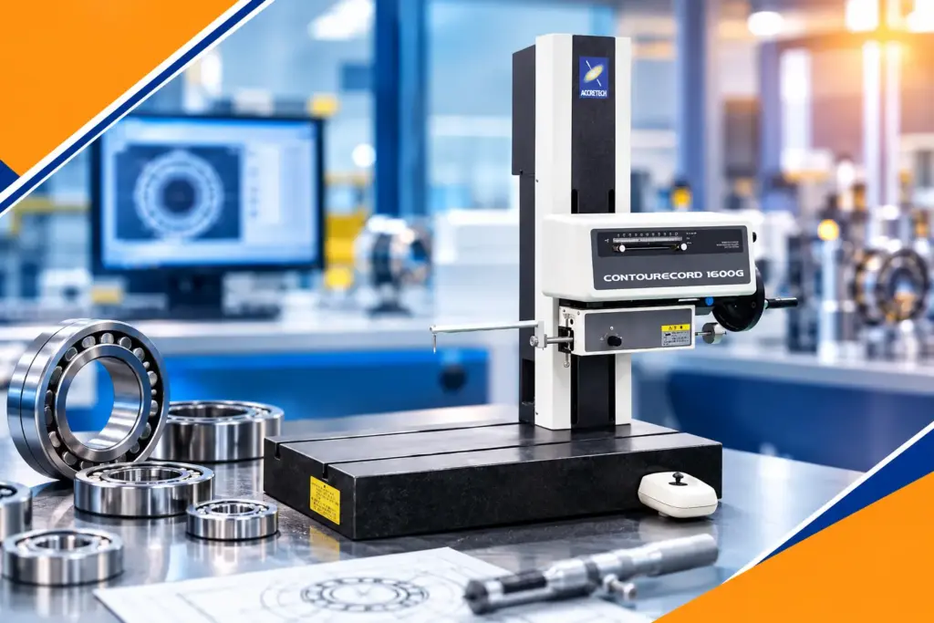
QS Metrology offers contour measuring instruments from ZEISS, including the Contourecord 1600G and SURFCOM NEX 040/030.
These systems are designed for precision contour measurement and profile analysis. Depending on the model and configuration, they can support the evaluation of accessible component profiles and selected geometric characteristics.
Which QS Metrology Contour Measuring Instruments Should Bearing Manufacturers Consider?
ZEISS Contourecord 1600G
The Contourecord 1600G is a contour measurement system designed for detailed two-dimensional profile analysis. Its published capabilities include profile measurement, software-based analysis, automatic element recognition, profile synthesis, and measurement-programme features.
For bearing manufacturers, its suitability depends on the workpiece geometry, required measurement range, stylus access, and inspection specifications.
ZEISS SURFCOM NEX 040/030
The SURFCOM NEX platform supports contour and surface measurement configurations, with sensor options and system arrangements depending on the selected model.
It may be relevant where manufacturers need to assess contour and surface measurement requirements within a compatible metrology workflow.
The most suitable system depends on whether the primary requirement is contour measurement, surface roughness measurement, or a combination of the two.
How Can QS Metrology Help Manufacturers Select the Right Solution?
Bearing manufacturers should begin with the profile drawings, required tolerances, representative samples, and inspection workflow.
QS Metrology can help assess the application and identify a suitable instrument configuration based on the geometry to be measured and the required analysis.
For applications requiring additional roundness, cylindricity, dimensional, or surface roughness inspection, the complete measurement plan should identify those requirements separately.
Explore the QS Metrology Contour Measuring Instruments page to learn more about available systems and discuss your bearing inspection requirements.
Conclusion: How Can a Contour Measuring Machine Improve Bearing Manufacturing Quality?
Bearing performance depends on the geometry of its critical features, including raceways, grooves, radii, shoulders, and profile transitions.
A contour measuring machine helps manufacturers evaluate these features using measured profile data rather than relying only on isolated dimensions or visual checks.
By introducing contour measurement at appropriate inspection stages, bearing manufacturers can identify geometric deviations earlier, investigate machining and grinding variation, and improve the consistency of profile verification.
The right solution must match the component geometry, required tolerance, stylus access, and inspection procedure. Contour measurement should also be combined with suitable roundness, surface roughness, and dimensional checks wherever the engineering specification requires them.
Looking to improve raceway and profile inspection in your bearing manufacturing process? Discuss your application with QS Metrology to evaluate a contour measurement solution suited to your components and quality requirements.
Discuss Your Bearing Profile Measurement Requirements
Frequently Asked Questions
What is a contour measuring machine used for in bearing manufacturing?
A contour measuring machine is used to measure and evaluate accessible component profiles, including suitable raceway cross-sections, grooves, radii, shoulders, and transitions. It helps manufacturers compare measured geometry with specified dimensions and profile requirements.
How does a contour measurement machine improve bearing quality?
A contour measurement machine provides quantitative profile data that can help identify geometric deviations, investigate machining or grinding variation, and verify specified features before components proceed to subsequent production stages.
Can a contour measuring instrument measure bearing raceway profiles?
Yes, a suitable contour measuring instrument can evaluate accessible two-dimensional raceway profiles and related geometric features. The exact capability depends on the bearing design, stylus access, measurement setup, and instrument configuration. A two-dimensional contour measurement does not automatically verify the complete three-dimensional raceway.
What is the difference between contour measurement and roundness measurement?
Contour measurement evaluates a defined profile, including features such as radii, grooves, angles, and steps. Roundness measurement evaluates deviations of a circular profile from a true circle. Bearing manufacturers may need both methods to verify different geometric requirements.
How can manufacturers choose the right contour measuring machine for bearing inspection?
Manufacturers should assess the component geometry, required profile features, measurement range, stylus access, tolerances, software capabilities, inspection volume, and technical support. Testing representative components against the actual inspection requirements helps confirm whether a system is suitable.