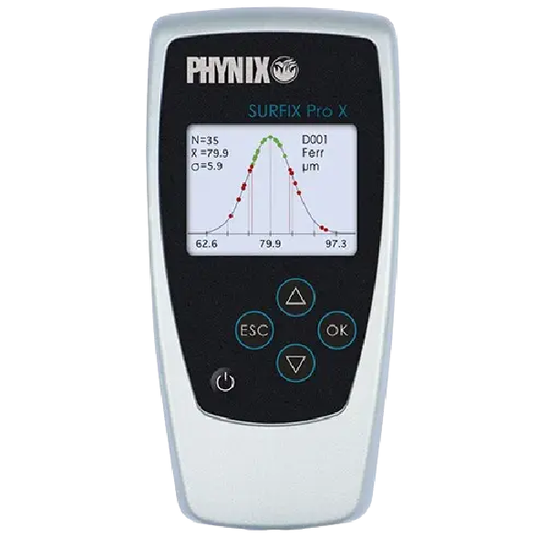
Surfix® Pro X Coating Thickness Gauge
The new premium product Surfix® Pro X features a large high-contrast color display and is apted to make large sets of measurements during production or in the laboratory.
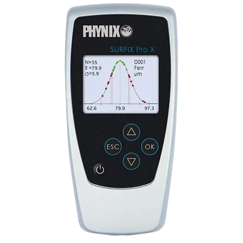
Surfix® Pro X
The new premium product Surfix® Pro X features a large high-contrast color display and is apted to make large sets of measurements during production or in the laboratory. Integrated USB and Bluetooth Interfaces make for an easy network Connection
Find Metrology Solutions In Strategic Industrial Locations
Key Features of Surfix® Pro X Coating Thickness Gauge

Multi‑Probe Support for Ferrous & Non‑Ferrous Substrates
High‑Resolution Colour Display
Large Data Memory & Statistics Handling
USB & Bluetooth Connectivity
Wide Measuring Range with Detachable Probes
- Detachable probe model
- Colour display
- Large data memory of up to 100,000 readings
- Up to 1,000 individual calibrations
- Free choice of file names
- Statistics
- USB and Bluetooth interface
- Multiple probe options
- Continuous measurement (up to 3 readings per second)
- DIN, ISO, ASTM, BS standards
- IP 52 (protection against dust and dripping water)
- Electroplating
- Paint shops
- Automotive industry
- Chemical industry
- Aerospace industry
- Ship building industry
- Tyre industry
- Quality management and final inspections
- Laboraties and research facilities
| Gauge | Supports multiple probes |
| Automatically identifies substrate type and activates appropriate measuring procedure | |
| Scan mode enables continuous measurement | |
| Automatic identification of probe type used | |
| Supports units µm and mils | |
| Memory | Large data memory for 100,000 readings, 1,000 selectable files, Free choice of filename |
| Saved readings and statistical values individually recallable | |
| Data Output | Data transfer via USB 2.0 und Bluetooth 4.0 |
| Statistics | Single and block value, selectable block size Parameter: n, x¯ , s, Min, Max, Kvar, cp, cpk |
| Calibration | Factory, Zeroing (1-point calibration), Zeroing and foil calibration (2-point calibration), Two-foil calibration, Zero offset: addition/subtraction of a constant value to/from the reading |
| Protection class | Protection class – IP 52 (proof against dust and dripping water) |
| Display | High resolution Color display Backlight, 4-digit alphanumeric Switchable backlight, Selectable between µm/mils |
| Standards | DIN, ISO, ASTM, BS |
| Measuring Principle | Magnetic induction principle (F-Mode) Eddy-current principle (N-Mode) |
| Limit values | Freely selectable; optical and acoustic signal if limit value is exceeded |
| Accuracy | Please refer supported probes |
| Resolution | Please refer supported probes |
| Warranty | 1 Years |
Supported Probes
| Range | 0 – 200 µm for Iron/Steel (FN & F models) 0 – 200 µm for Non-Ferrous metals (FN and N Models) |
| Substrate | Ferrous and Non-Ferrous |
| Tolerance | ± (0.7 µm + 1 % of reading) |
| Resolution | 0.1 µm or < 0.2 % of reading |
| Min. Area of measurement | 5 mm x 5 mm |
| Minimum radius of curvature | Convex 1.5 mm, Concave 5 mm |
| Minimum thickness of substrate | Iron/Steel: 0.2 mm Non-ferrous metals: 50 µm |
| Surface Temperature | -15 °C to 60 °C |
| Range | 0 – 1,500 µm for Iron/Steel (FN & F models) 0 – 1,500 µm for Non-Ferrous metals (FN and N Models) |
| Substrate | Ferrous (FN/F) and Non-Ferrous (FN/N) |
| Tolerance | ± (1 µm + 1 % of reading) |
| Resolution | 0.1 µm or < 0.2 % of reading |
| Min. Area of measurement | 5 mm x 5 mm |
| Minimum radius of curvature | Convex 1.5 mm, Concave 5 mm |
| Minimum thickness of substrate | Iron/Steel: 0.2 mm (FN and F Model) Non-ferrous metals: 50 µm (FN and N Model) |
| Surface Temperature | -15 °C to 60 °C |
| Minimum ID for measurement (for FN 1.5/90) | 12.5 mm |
| Range | 0 – 1,500 µm for Iron/Steel 0 – 1,500 µm for Non-Ferrous metals |
| Substrate | Ferrous and Non-Ferrous |
| Tolerance | ± (1 µm + 1 % of reading) |
| Resolution | 0.1 µm or < 0.2 % of reading |
| Min. Area of measurement | 5 mm x 5 mm |
| Minimum radius of curvature | Convex 1.5 mm, Concave 5 mm |
| Minimum thickness of substrate | Iron/Steel: 0.2 mm (FN and F Model) Non-ferrous metals: 50 µm (FN and N Model) |
| Surface Temperature | -15 °C to 60 °C |
| Minimum ID for measurement | 12.5 mm |
| Range | 0 – 3,500 μm – For Iron/Steel 0 – 3,000 μm – For Non-Ferrous substrates |
| Accuracy | ± 3 μm or ± 3 % of reading (whichever is greater) |
| Resolution | 1 μm for 0 to 1,000 μm 2 μm for 1,000 to 2,500 μm 5 μm for 2,500 to 3,500 μm |
| Min radius for convex surface | 5 mm |
| Min radius for concave surface | 50 mm |
| Min measuring area | 10 mm X 10 mm |
| Range | 0 – 10 mm – For Iron/Steel |
| Accuracy | ± 10 μm or ± 3 % of reading (whichever is greater) |
| Min radius for convex surface | 5 mm |
| Min radius for concave surface | 50 mm |
| Min measuring area | 10 mm X 10 mm |
How Surfix® Pro X Coating Thickness Gauge Work?
The Surfix® Pro X Coating Thickness Gauge works by using non-destructive measurement principles to determine the thickness of coatings on different substrates. For ferrous (magnetic) substrates, it uses magnetic induction, and for non-ferrous (non-magnetic) substrates, it uses eddy current technology. A probe is placed on the coated surface, and the gauge detects changes in the magnetic field or induced currents caused by the coating layer. These signals are converted into thickness values displayed on the gauge’s high-resolution screen. The instrument can store measurements, calculate statistical data, and transfer results via USB or Bluetooth, making it ideal for quality control, inspection, and maintenance of painted, plated, or coated surfaces.
Locations We Serve
QS Metrology provides Surfix® Pro X Coating Thickness Gauge across India, serving all major industrial regions, including:
Delhi NCR, Rajasthan, Punjab, Uttar Pradesh, Himachal Pradesh, Uttarakhand, Jammu & Kashmir
Why Choose QS Metrology?
High-Precision Measurement
Advanced Probe & Software Technology
Durable & Reliable Design
Wide Industry Applications
Expert Support & Service
FAQs
It is used for non‑destructive measurement of coating thickness on painted, plated, anodized, or protective surfaces.
It supports ferrous (magnetic) and non‑ferrous (non‑magnetic) substrates using appropriate measurement principles.
It uses magnetic induction on ferrous metals and eddy current technology on non‑ferrous metals to determine coating thickness.
Yes — it offers data storage, statistics handling, and USB/Bluetooth connectivity for easy result transfer.
It provides a wide measurement range suitable for thin to thick coatings across various industrial applications.
Yes — with a high‑resolution color display and intuitive interface, it is easy to operate even for field and shop‑floor use.
Industries We Serve

Automotive

Medical Device & Pharmaceutical

Aerospace

Electronic & Electric Component

Chemicals & Petrochemicals

Metal Foundries & Casting

Energy, Power & Renewables
