5 Common Measurement Challenges in Tool & Die Industry (And How CMM Solves Them)
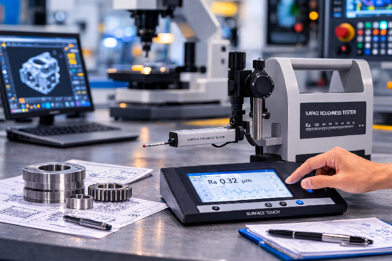
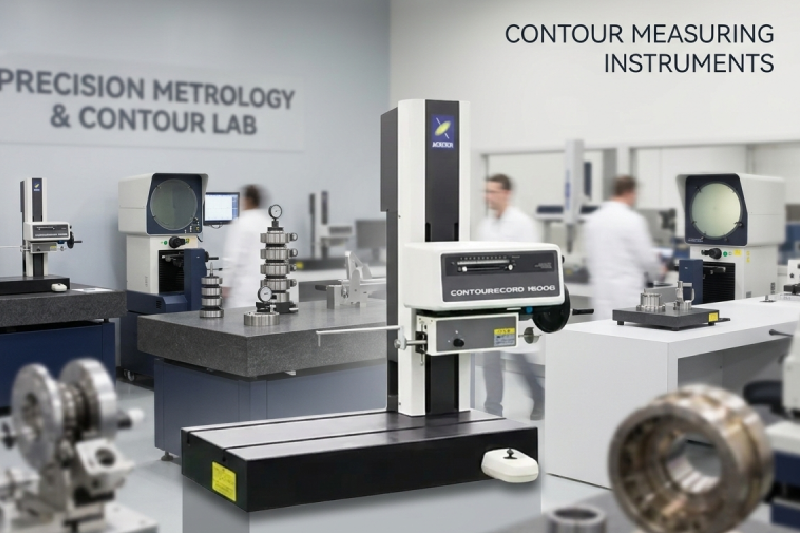
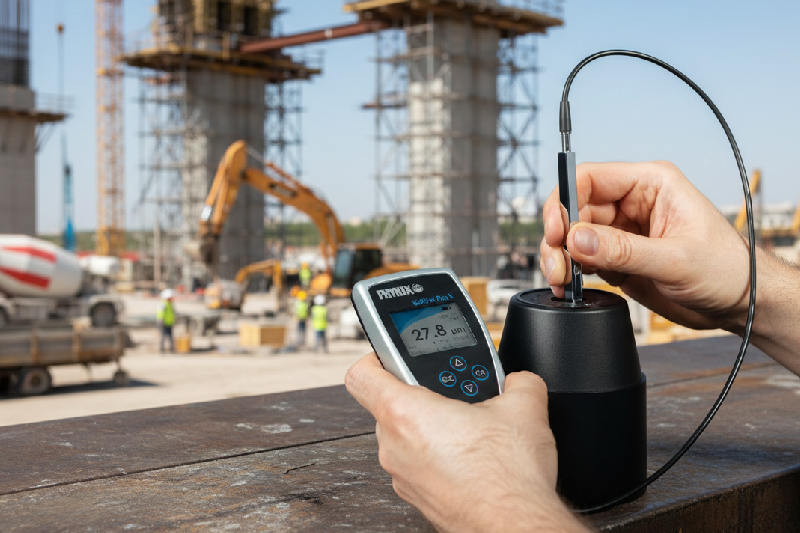
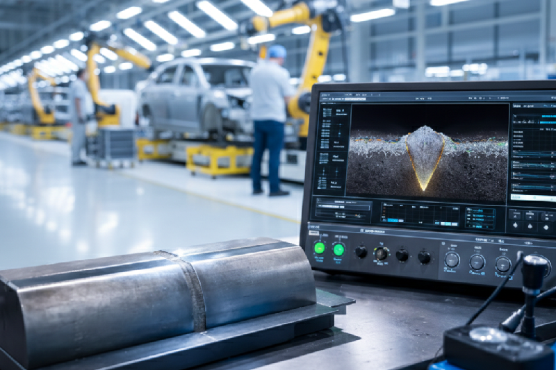
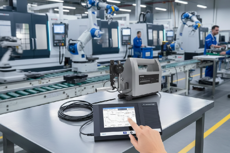
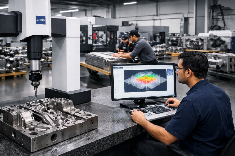
In India’s fast-evolving manufacturing ecosystem, the Tool & Die industry plays a critical role in supporting automotive, aerospace, electronics, and heavy engineering sectors. Whether it’s high-precision dies in Gurgaon or mold manufacturing units in Noida, maintaining dimensional accuracy is no longer optional—it’s a competitive necessity. However, many tool rooms and mold manufacturers across Faridabad, Ghaziabad, Ludhiana, and Baddi still face recurring measurement challenges that impact quality, cost, and delivery timelines. This is where a coordinate measuring machine—especially advanced solutions like ZEISS CMM and portable CMM machine—becomes a game-changer. Let’s explore the 5 most common measurement challenges and how modern CMM technology solves them. 1. Inconsistent Measurement Accuracy The Challenge Traditional tools like vernier calipers, micrometers, and height gauges often lead to inconsistent results. Manual errors, operator dependency, and limited precision can result in dimensional deviations—especially in complex dies and molds. Major automotive manufacturing clusters are located in cities such as Gurugram, Manesar, Faridabad, and Noida in North India. These cities host hundreds of automotive OEM suppliers and component manufacturers that supply parts to major automobile brands. The Impact Increased rejection rates Poor fitting of components Loss of client trust The Solution A coordinate measuring machine eliminates human error by providing automated, highly accurate measurements. Systems like ZEISS CMM offer micron-level precision, ensuring every dimension is verified with consistency. For manufacturers in high-demand clusters like Gurgaon, this translates into better product reliability and fewer reworks. 2. Difficulty in Measuring Complex Geometries The Challenge Modern molds and dies often include intricate contours, freeform surfaces, and tight tolerances. Traditional measurement tools simply cannot capture these complex geometries accurately. The Impact Design mismatches Tool failure during production Increased trial-and-error cycles Machine shops often use a surface roughness tester to evaluate the smoothness of machined surfaces before components are delivered to clients. Precision shafts, hydraulic components, valves, and mechanical fittings are commonly tested using surface roughness measuring instruments. The Solution A coordinate measuring machine uses advanced probing systems to measure 3D geometries with high accuracy. With ZEISS CMM, manufacturers can inspect complex surfaces, curves, and profiles with ease. Additionally, a portable CMM machine allows on-site inspection of large or complex parts, reducing the need to move heavy tools. 3. Time-Consuming Inspection Processes The Challenge Manual inspection methods are slow and labor-intensive. Measuring multiple dimensions across complex tools can take hours—impacting production timelines. The Impact Delayed deliveries Reduced productivity Increased labor costs The Solution A coordinate measuring machine significantly reduces inspection time through automation and multi-point measurement capabilities. Programs can be saved and reused, enabling faster repeat inspections. In industrial hubs like Faridabad and Ghaziabad, where production speed is critical, adopting ZEISS CMM helps businesses meet tight deadlines without compromising quality. 4. High Rework and Scrap Rates The Challenge Even minor measurement errors can lead to significant defects in molds and dies. Without accurate inspection, faulty tools move into production, resulting in costly rework or scrap. The Impact Increased material wastage Higher production costs Reduced profitability The Solution Using a coordinate measuring machine, manufacturers can detect deviations early in the inspection stage. This ensures that only accurate tools proceed to production. A portable CMM machine is especially useful for in-process inspections, allowing immediate corrections on the shop floor—minimizing scrap and rework. 5. Lack of Digital Measurement Data & Reporting The Challenge Manual measurement methods often lack proper documentation and traceability. This becomes a major issue when dealing with OEM clients or export orders requiring detailed inspection reports. The Impact Difficulty in quality audits Poor traceability Loss of business opportunities The Solution Modern coordinate measuring machine systems generate detailed digital reports, including 3D models, tolerance analysis, and graphical insights. With ZEISS CMM, manufacturers can provide professional inspection reports that meet global standards—helping tool rooms in Ludhiana and Baddi compete in international markets. Why Indian Tool Rooms Are Moving Towards CMM? Across India, forward-thinking manufacturers are rapidly adopting: coordinate measuring machine for precision inspection ZEISS CMM for advanced metrology solutions portable CMM machine for flexible, on-site measurement This shift is driven by: Increasing demand for high-precision components Growing export opportunities Need for automation and Industry 4.0 integration Measurement challenges in the Tool & Die industry are not just technical issues—they directly impact your cost, quality, and reputation By investing in a coordinate measuring machine, especially trusted systems like ZEISS CMM or a flexible portable CMM machine, businesses can: Improve accuracy Reduce rework Speed up production Win more high-value contracts Checkout our CMMs and Book a Free Demo